
Fort Emplacements and FDM: making Castle Doctrine
A while back I started the 1A2A3D project, a group of objects that took concepts from American gun culture and used 3D-printing to highlight some of the absurdities of it by making objects derived of those concepts. These I’d mostly planned out in advance, having drafted the ideas as on the first session of brainstorming for this project, but there was one idea that I had neither the time nor facilities to properly make in 2020. The idea was pretty simple -
3D-PRINT A CANNON
But it more complicated in execution than I expected. What design of cannon do I print? How do you make a cannon? What are the parts of a cannon? How should I do this? And that’s when it hit me, I was living in an area notorious for its cannons.
During 2020 I was living in Somerville Massachusetts, home to Tufts university and a park formerly owned by Nathan Tufts, Powderhouse Square. Pictured is the park’s namesake, the Powderhouse. This freestanding structure - The oldest stone building in the state - was once the largest gunpowder magazine in Massachusetts. Prior to the start of the American Revolution it was the site of an incident that caused the Powder Alarm. On September 1st, 1774, the contents of the powderhouse were seized by the British and taken to the nearby Castle Williams (now Fort Independence), an action that caused the colonists to fear in earnest that war was coming.
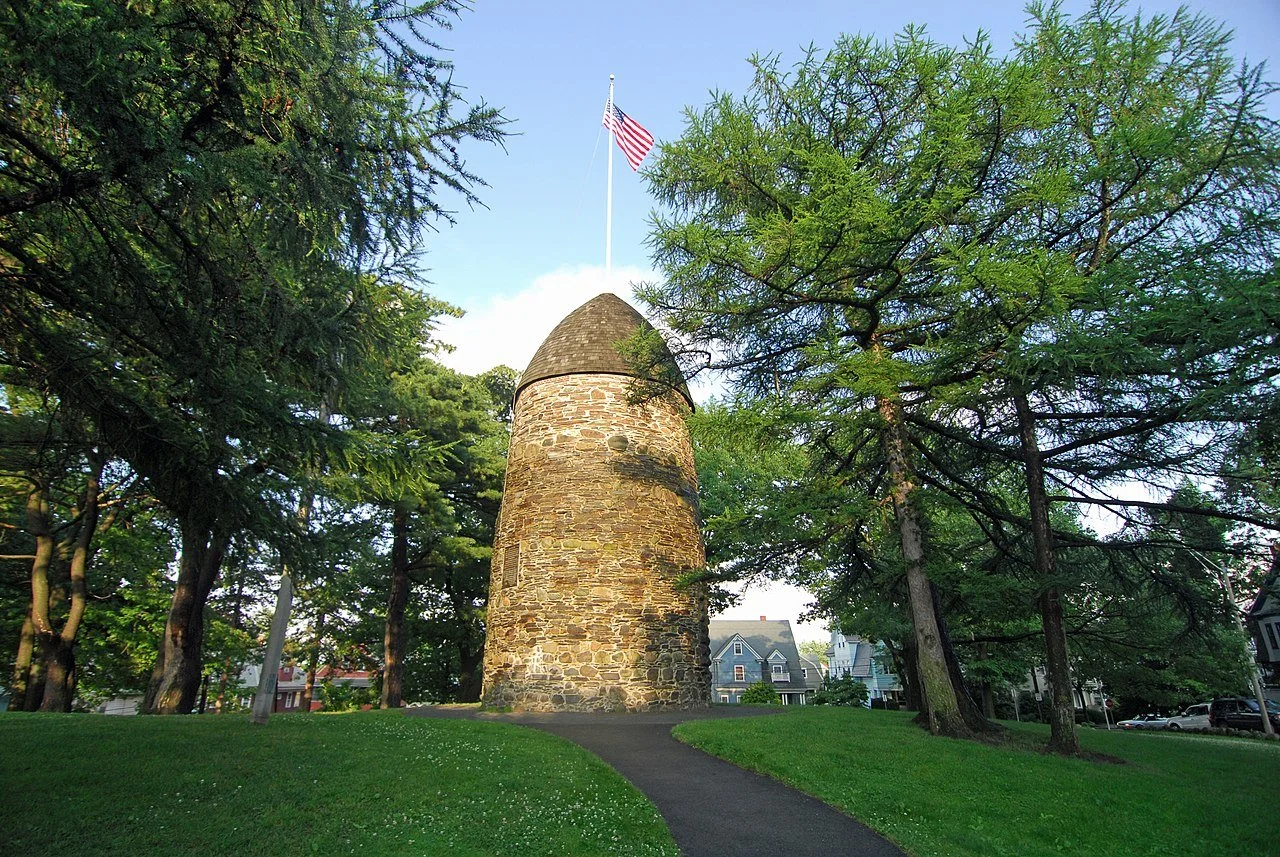
Photo by Eric Kilby, CC 2.0 via Wikimedia
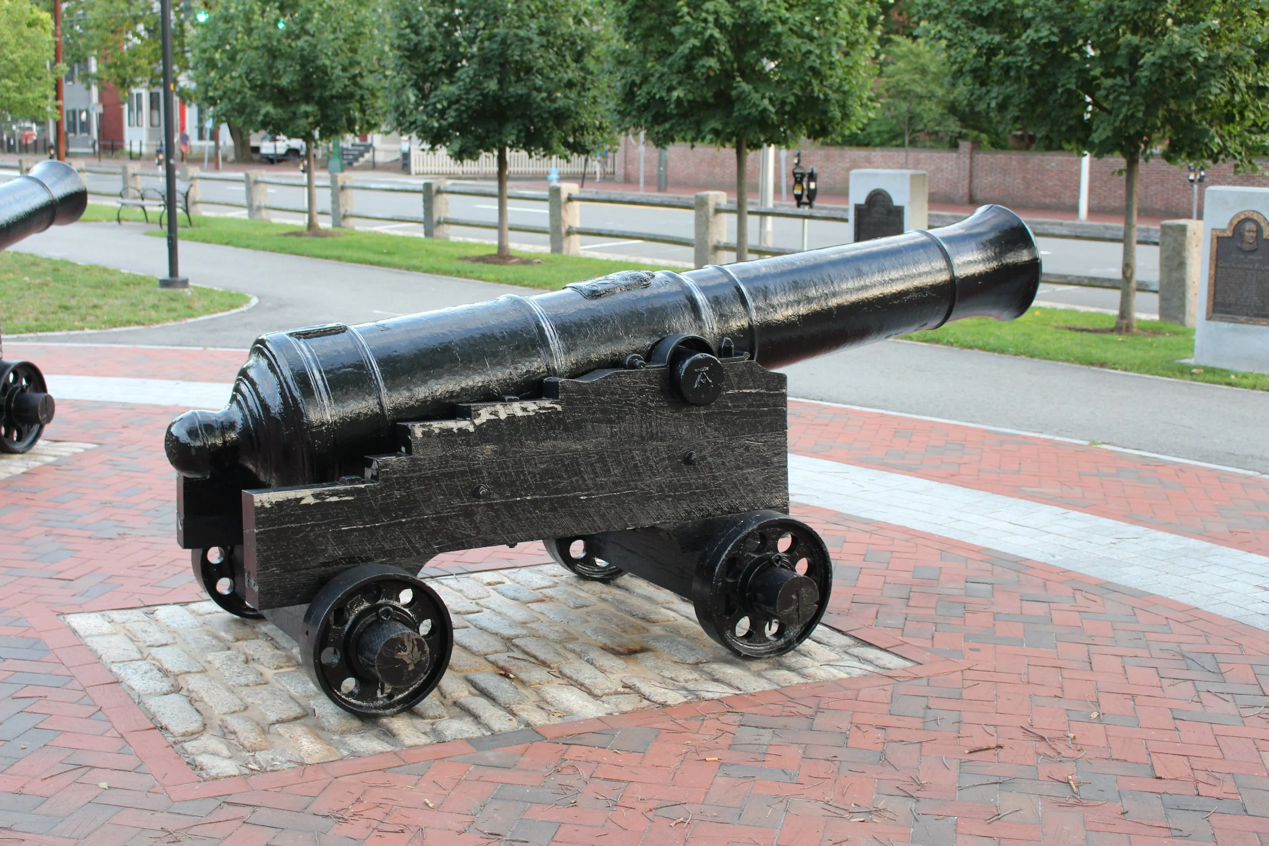
Just one town down from Somerville is is Cambridge Massachusetts, home to Harvard university and the closeby Cambridge Common, a large park that hosts a number of cannons seized from Castle Williams. These large cannons, like many others, now sit in a park acting as a local monument.
Specific objects from the time persist, these cannons for instance. They are armaments that helped found the United States and that are still revered today because of that role.
With that in mind, I started planning out how to make one. And almost 2 years later I started it in earnest.
To begin, I needed a design.

Lucky for me there has been quite a bit of work done on the design of cannons. In diving into the rabbit hole of cannon history and fabrication, I stumbled upon the book Artillery through the Ages which highlights artillery used primarily in the United States. A number of the diagrams reference another text, A Treaties of Artillery, written in 1757 by mathematician John Muller. Jackpot.
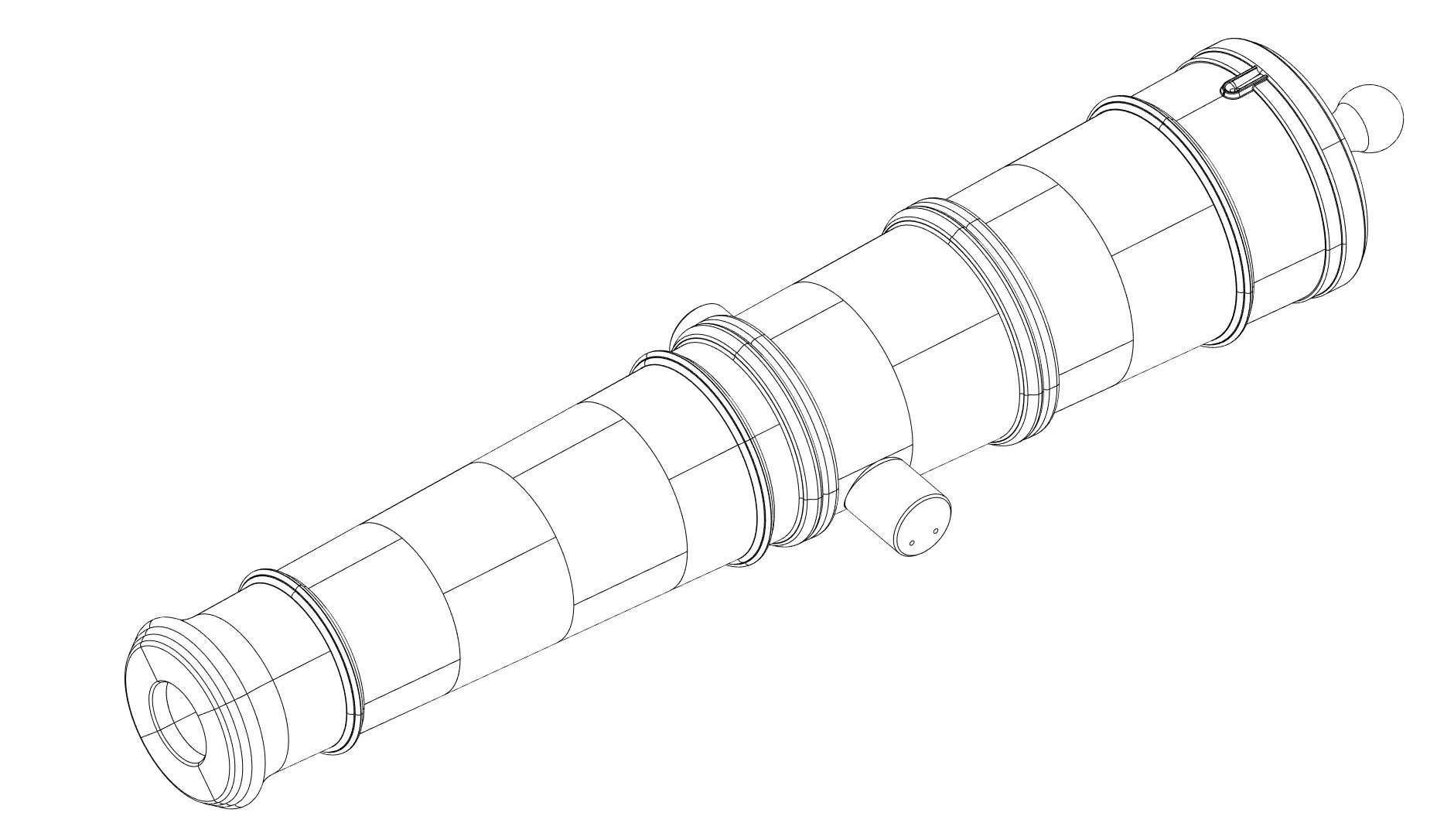
A Treaties of Artillery contains a number of annotated designs of cannons used during the period. Using these diagrams I modeled an emplacement gun (A cannon that would have been used in fort or other stationary situation) in CAD and got to figuring out how to 3D-print the darn thing.

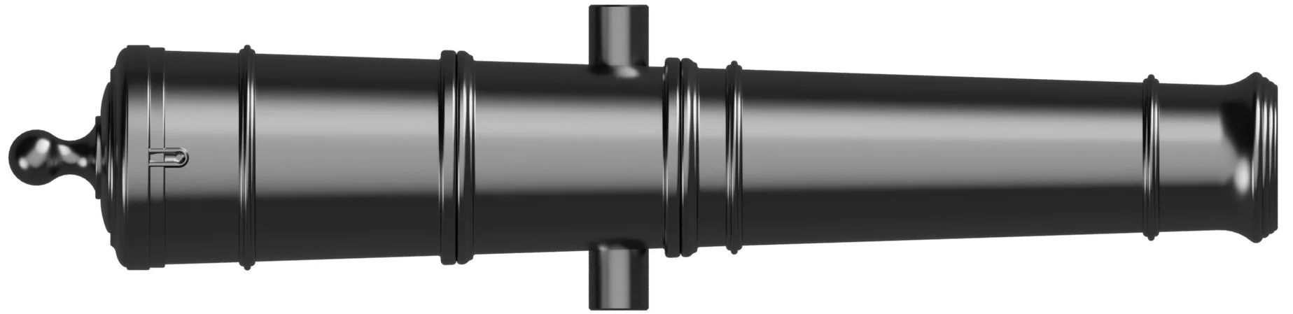
(Above) - A diagram of a 30lbs cannon pulled from A Treaties of Artillery
(Below) - A render of the modeled cannon pulled from CAD.
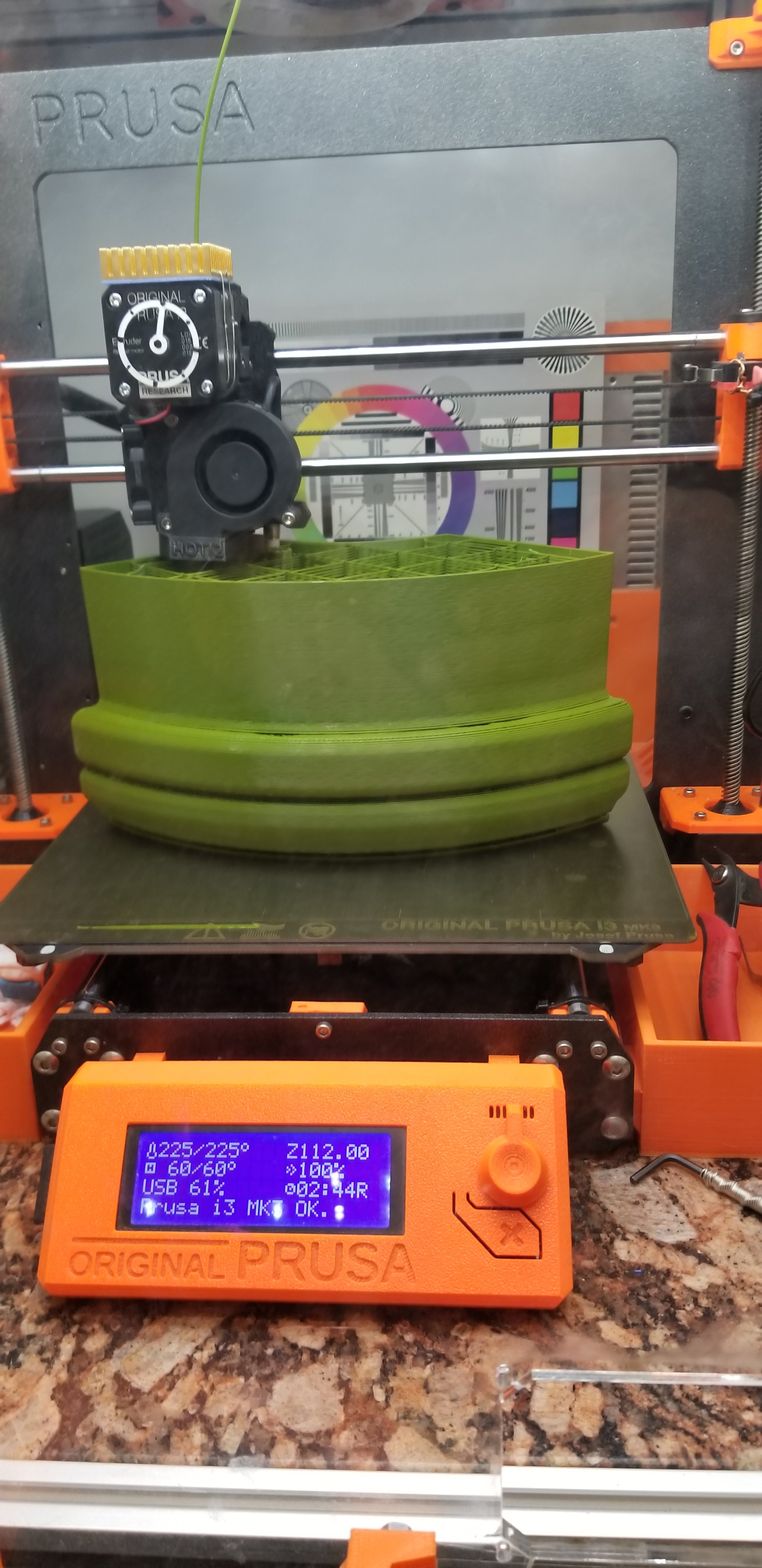
The main problem with making a cannon is scale. The cannon, as designed, was 6ft long and roughly 2ft at it’s widest point. My 3D printer, a Prusa i3 MK3, can only handle objects at roughly 8” cubed. To make a printed cannon with the tools I had available, I had to borrow a technique used by 3D-printing enthusiasts, breaking up the print into parts to then assemble into a larger object. In the case of this cannon, making objects to fit in my 25×21×21 cm build area, it was going to be 52 prints.
The basic concept was this - slice the barrel into quarter-rounds that could be assembled into rings and then run a length of all-thread through the whole object to hold all the rings together. To test this I made a number of test prints, which allowed me the added opportunity to really dial in the print settings.
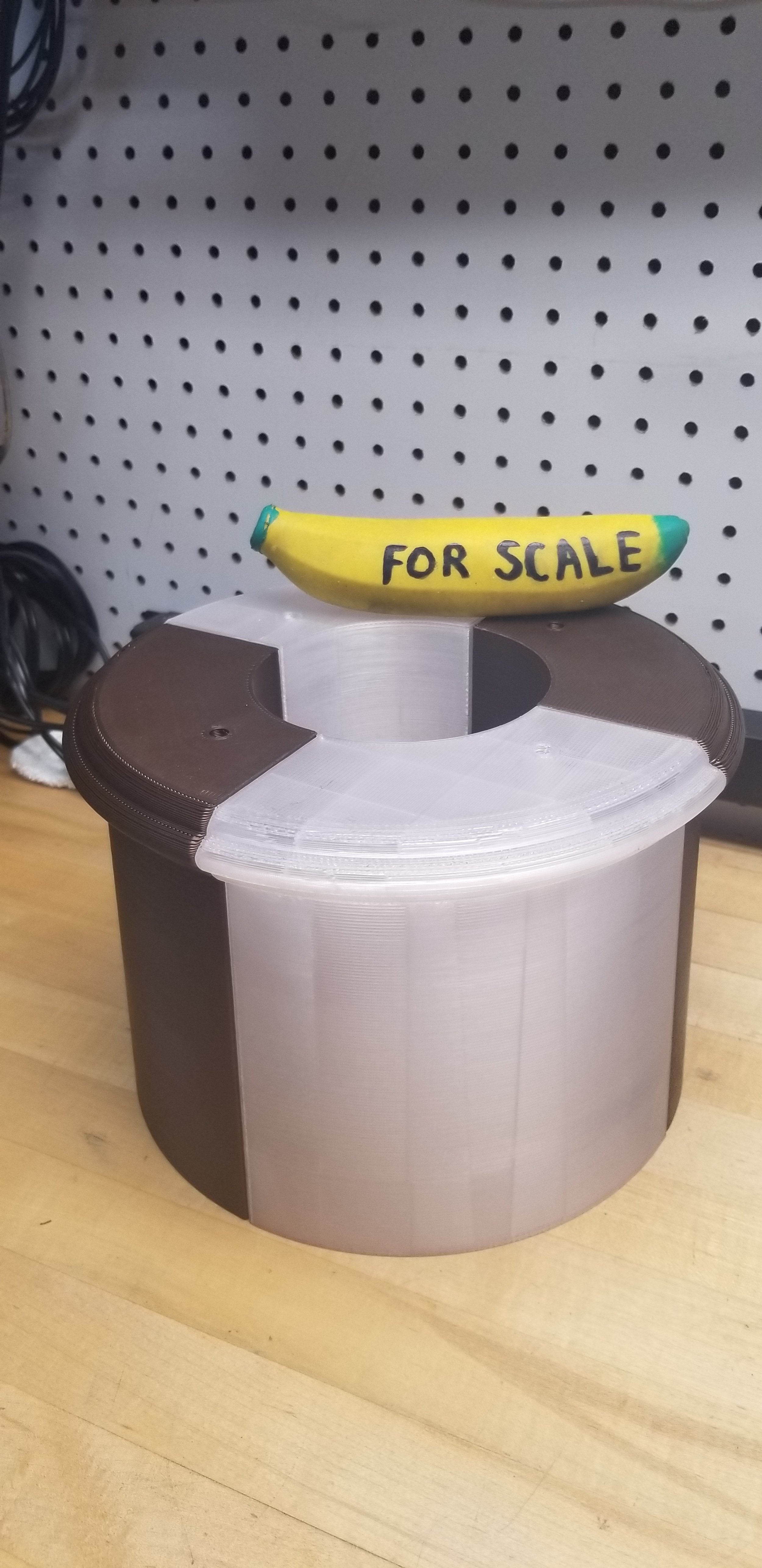
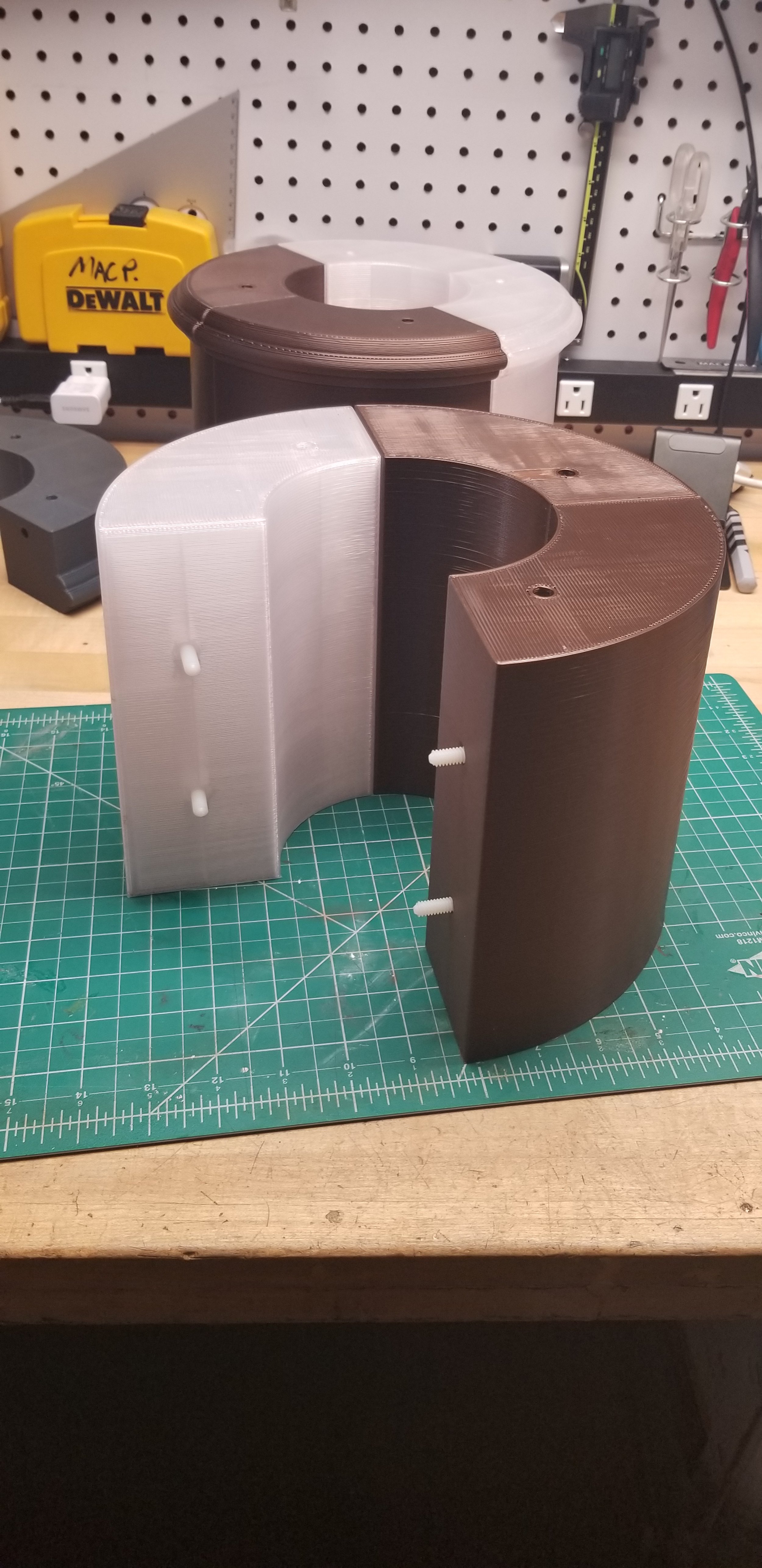
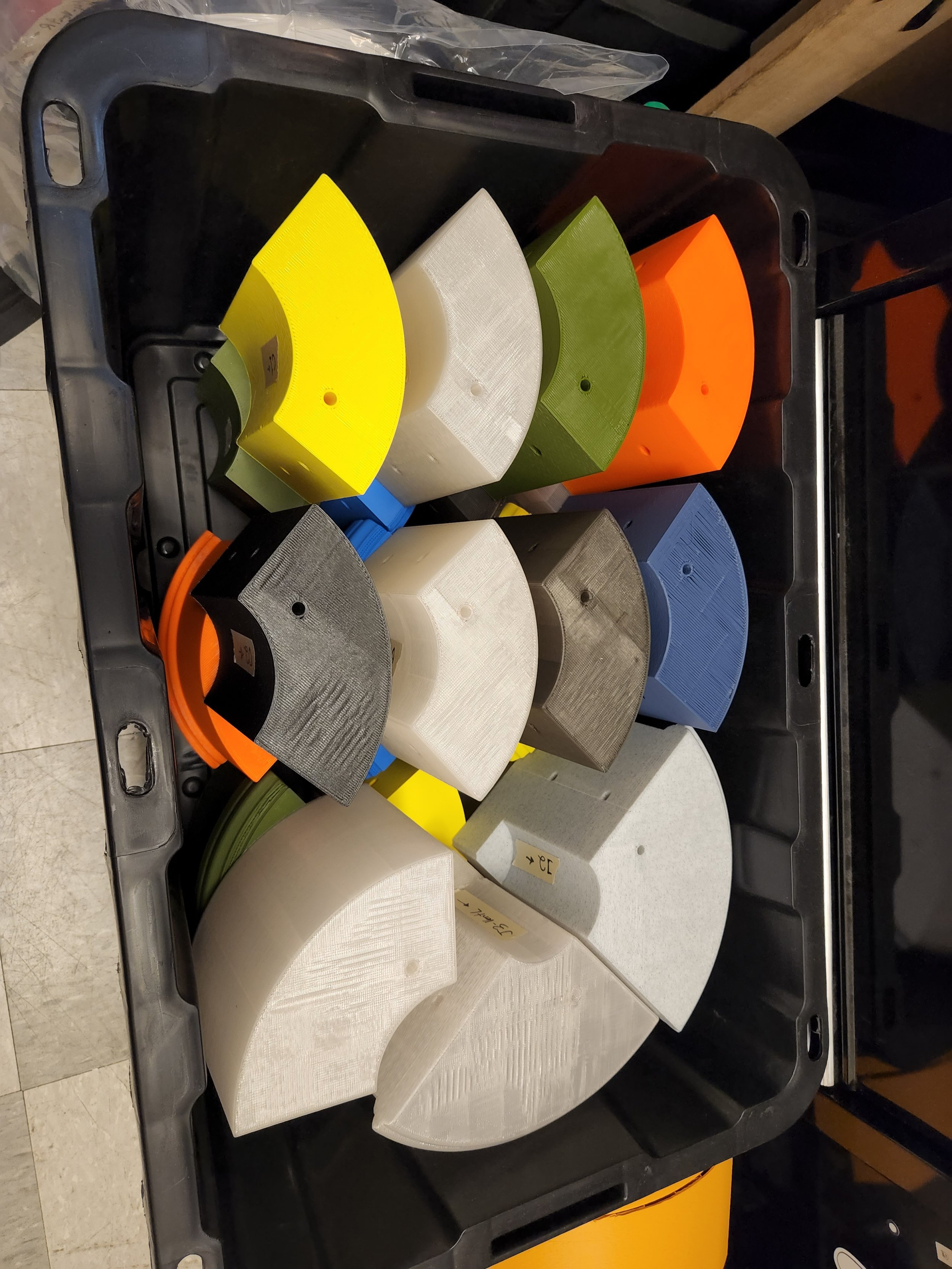
I cannot stress enough how helpful this step was. By doing multiple rounds of making test parts and revising my settings I was able to dramatically cut down the amount of time and material each component would require. In place of the stock 0.4mm nozzle, I settled on a 0.8mm nozzle, which allowed for a 400% increase in nozzle flow rate. On top of that, each component was printed at a 0.6mm layer height and a wisp-like 2.5% infill. For comparison, one of the B sections (Shown above on the left) printed with stock settings (0.4mm nozzle, 0.2mm layer, 15% infill) had a print time of 29 hours and consumes 381g of filament. Using tuned settings, that same part took 7 hours and 251g of filament. I needed every bit of savings I could get on an endeavor of this scale and that time spent tuning payed for itself many times over.
And that’s how the project sat for about 2 years.
I didn’t have the space or the reason to fully make this project… Until I came to grad school.
Then it was time to make it. 😎
Time-lapse showing the printing of one of the H sections.
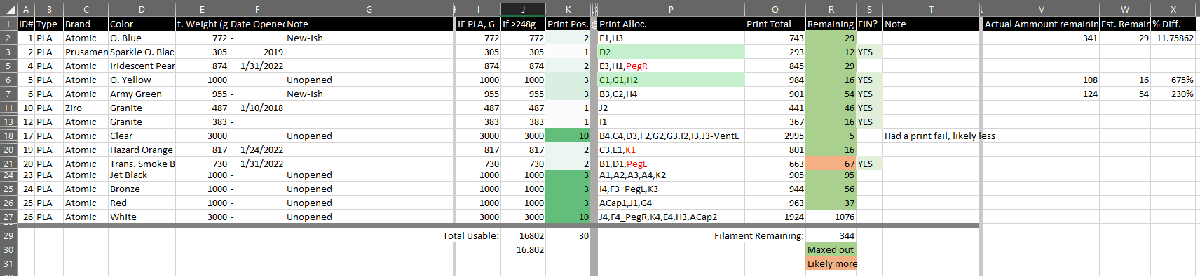
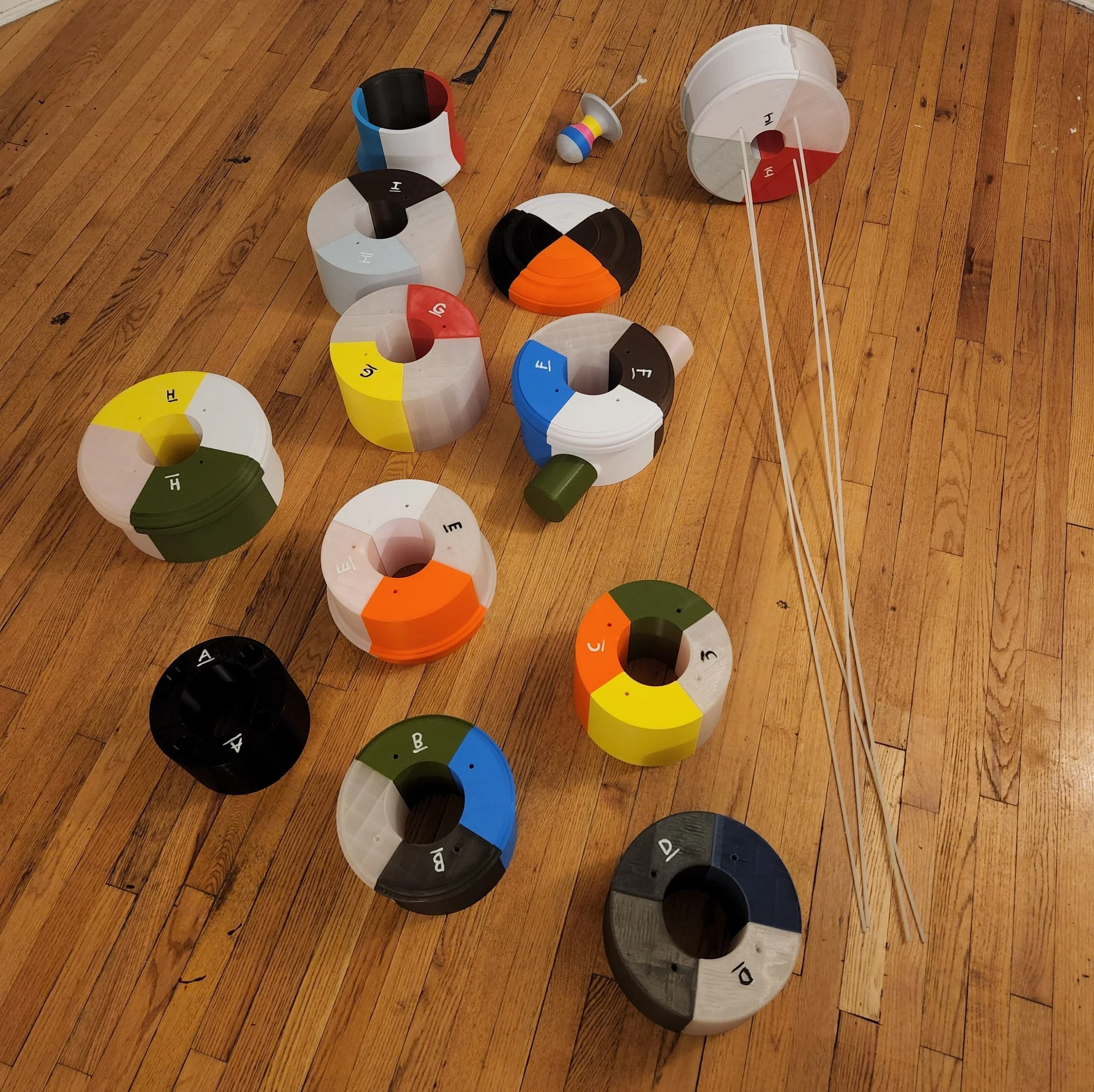
One of the first things I did was catalog all of the filament I had on hand and calculate how much I was going to need. Throwing all parts into the slicer to get filament usage estimates and determine how much time would be needed for each print. Again, very helpful, would recommend.
This, of course, was a ton of printing. Theoretically, I could fit in 4 prints a day, each averaging 8 hours. Realistically this ended up working out to more like 2 prints a day, where I’d come into the studio to work and start a print in the morning, and by the end of day start another to run overnight. All told this process took about 2 months start to finish, allowing for print failures and swapping the machine to other projects. Tally on print time worked out to 304 machine hours, using roughly 13kg of filament.
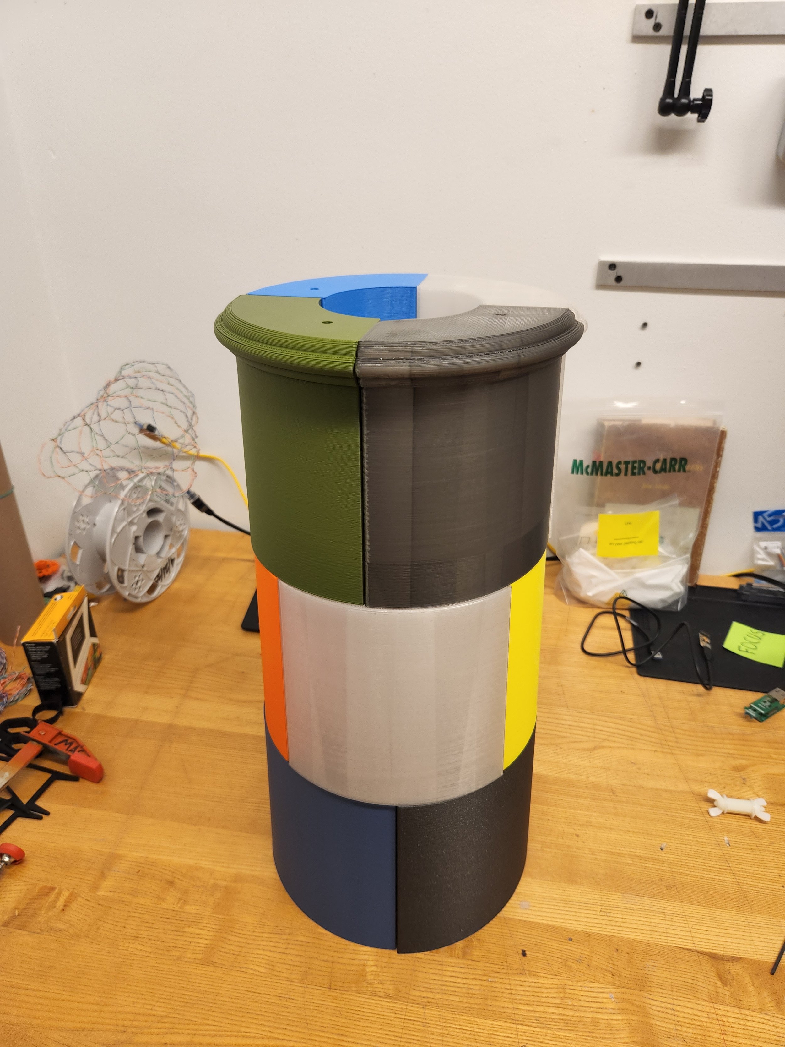

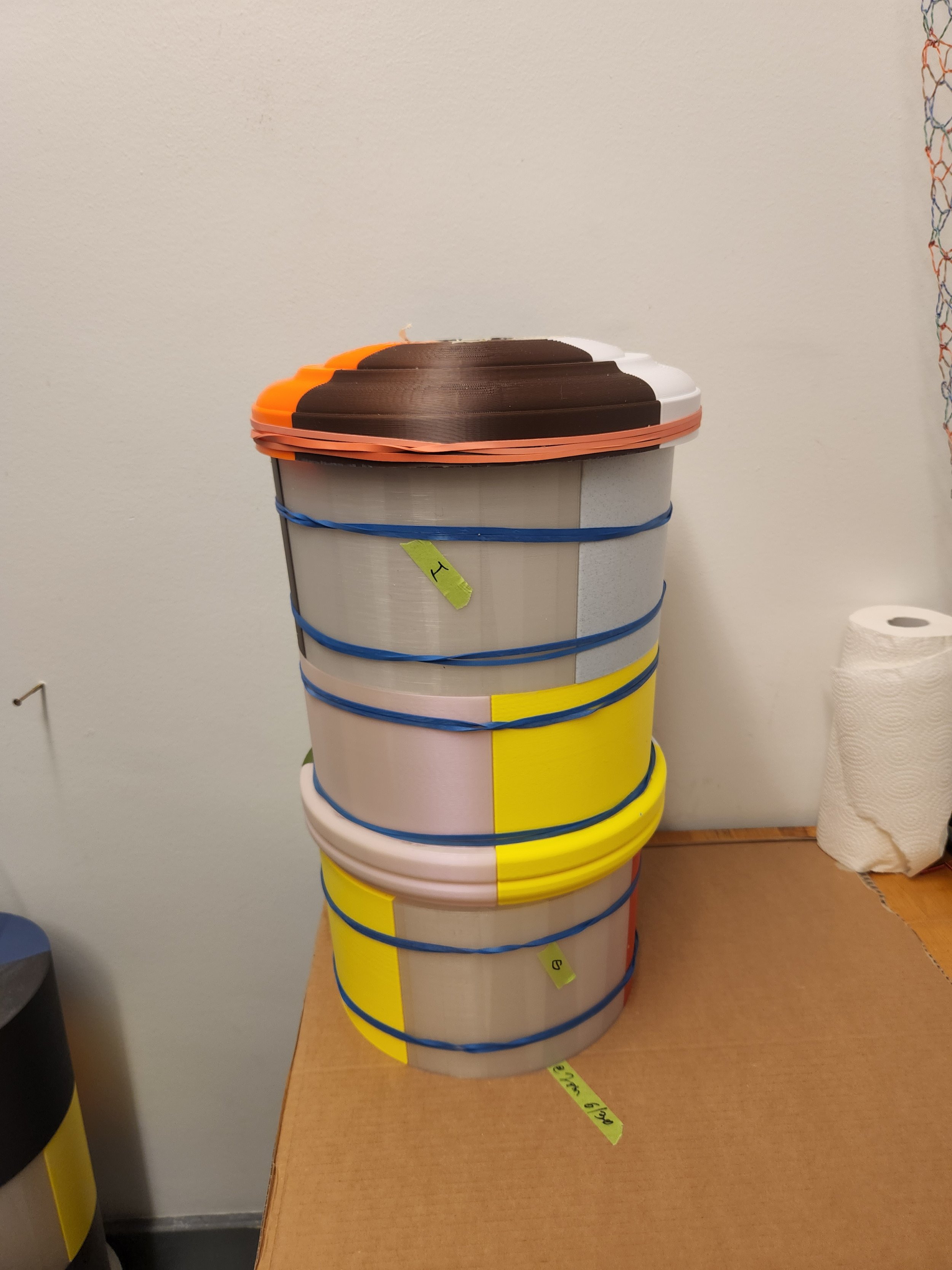
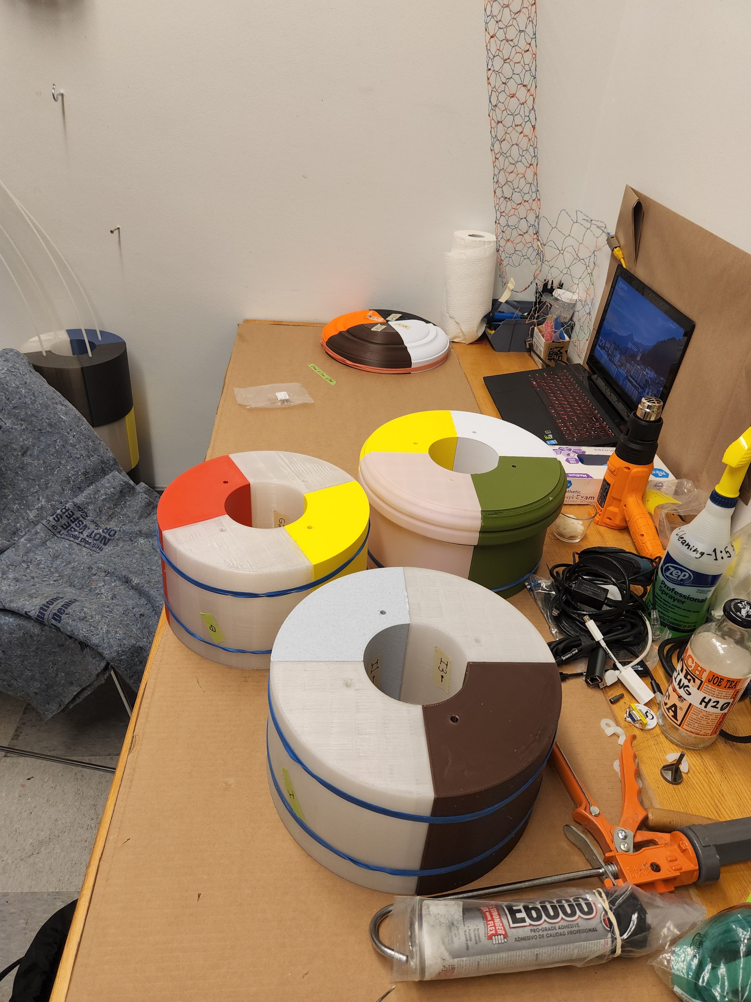
Once all the components were printed, I could set out assembling the individual sections. To assemble the quarters of each of the torus sections, I inserted 1/4-20 1” nylon studs into recesses on the mating faces and held them in place with a dab of E6000 glue (Did you know you can buy this in cartridges’ made for caulk guns?). Between the flat faces, I applied a liberal amount of E6000 and held the pieces together with oversized rubber bands to cure.
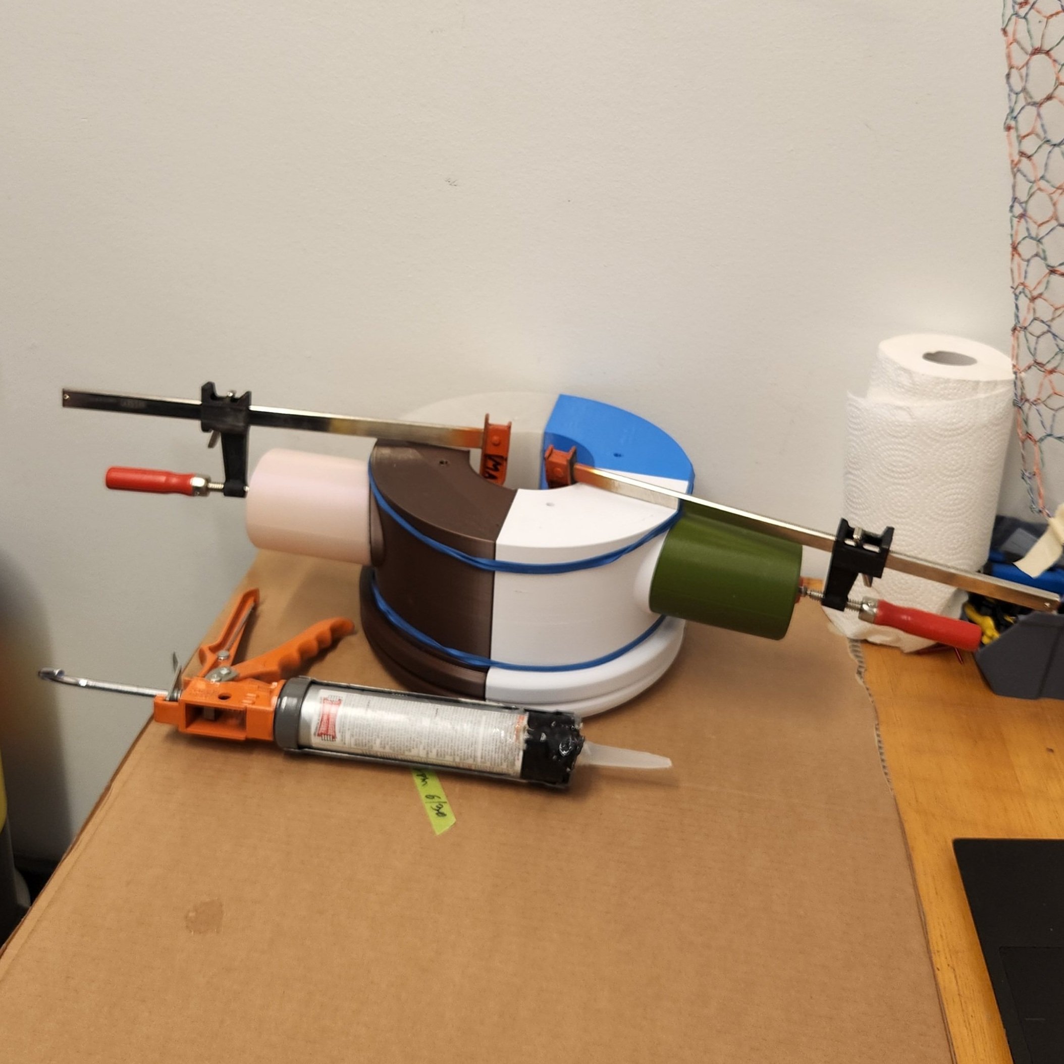
And once that was all together, it was only a matter of holding each of the slices together. To achieve this, I used 4 lengths of 1/4-20 nylon threaded rod that run through the whole of the assembly and seat into nylon coupling nuts embedded in a slice at the end of the cannon. To tighten it in, nylon wing nuts tighten down the rod, aligning the slices and keeping them in tension.
As a note - All of this nylon hardware could have easily been steel, which is far easier to source. That said, having a cannon that won’t set off a metal detector is endlessly amusing to me.
Neat.
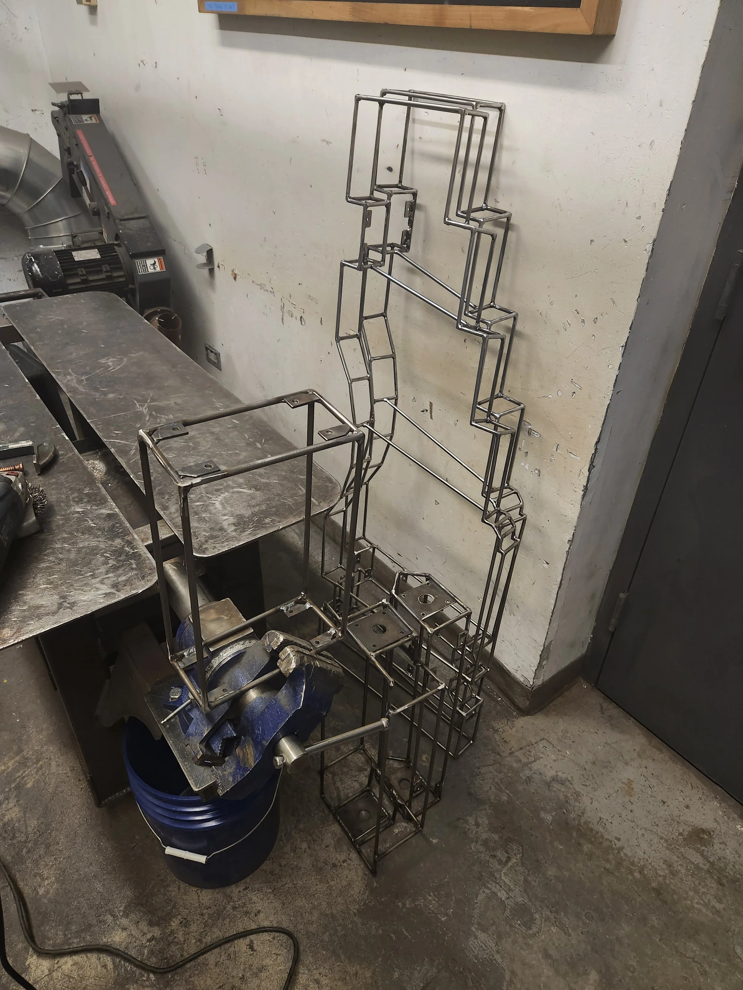
But of course, I couldn’t be done there. I was making a fortification emplacement, which is defined by the type of carriage it was mounted on. So I devised a carriage to match, drawing inspiration from the multitude of wireframes I’d worked with in designing.
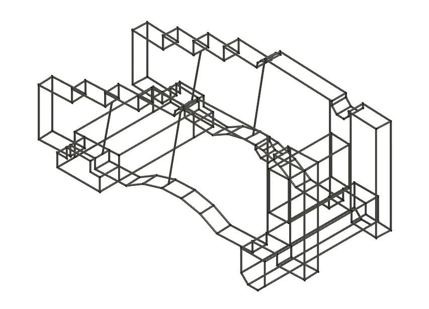
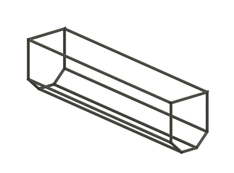
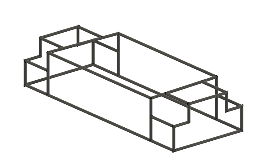
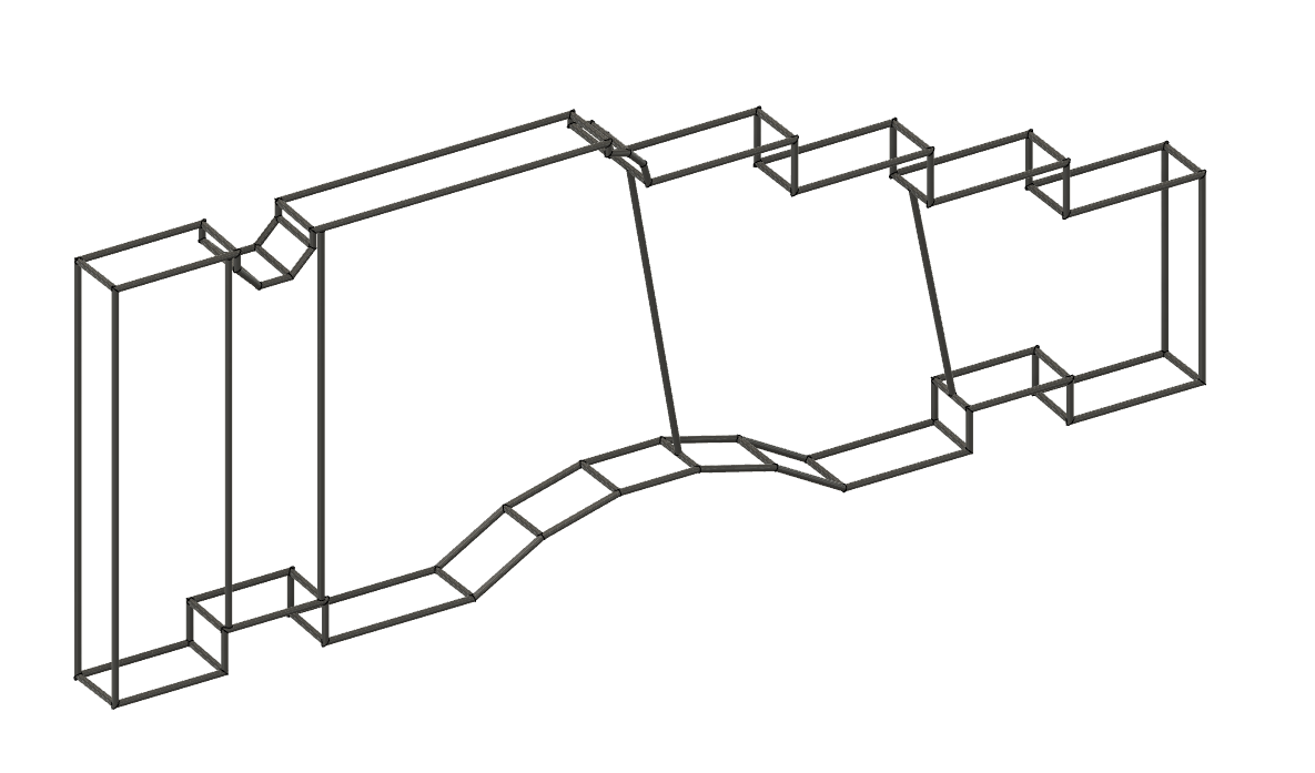
I then printed out these renders at scale on a plotter and used them as templates to fabricate the frame out of.

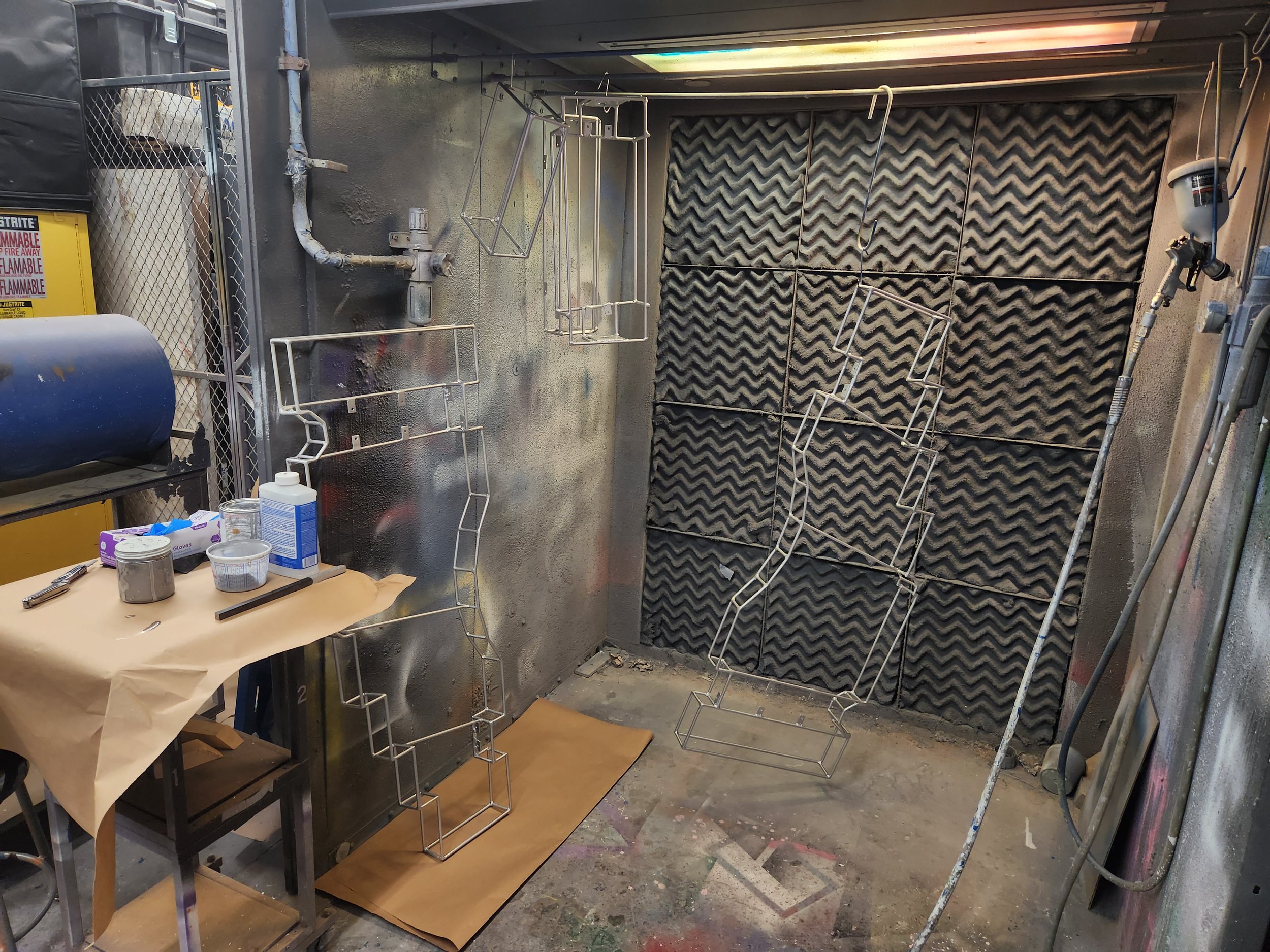
Once the frame was welded together, I ground down some of the knobbier of the welds and then prepped and painted the whole thing.
The final step was adding axels and wheels. Harbor Freight to the rescue.

Nice.
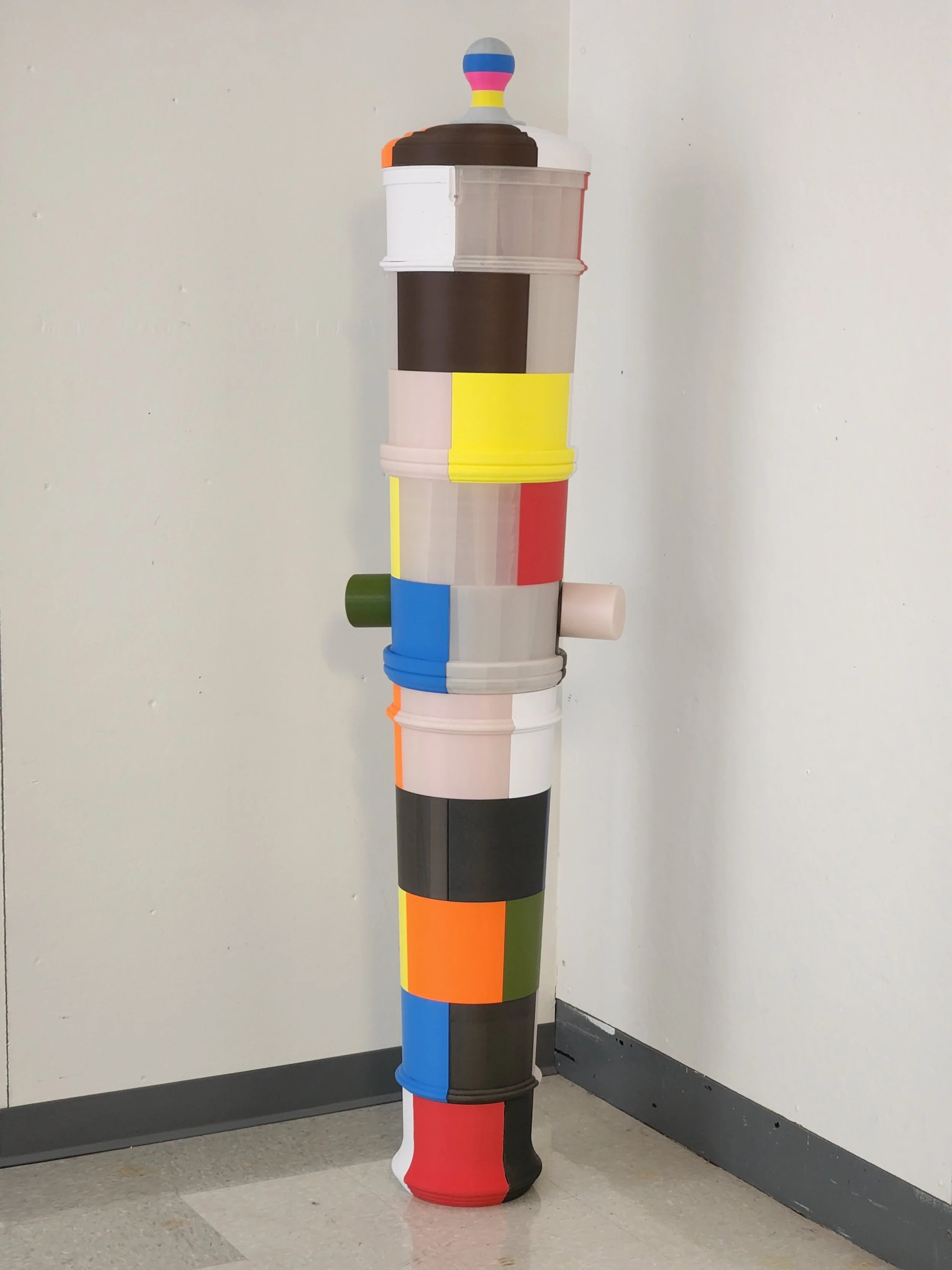
And just like that, this enormous project is done. At time of writing, It’s currently installed in a gallery (Bert Green Fine Arts), which is still wild to me. Going from this absurd concept to a finished object is one of my favorite things about art, and a project like this typifies that whole experience for me.
Oh, and of course, in the spirit of 3D-printed firearms, below are all of the files that I used to make the cannon body. Included are the .STL’s, a .STEP file, and a readme with step by step assembly instructions all available via a Creative Commons Attribution-NonCommercial 4.0 International (CC BY-NC 4.0).
Download your own cannon! - [ZIP file, 3.85MB]
Enjoy!