
An (overbuilt) 10" mini rack for a LAN Party
I was about to host a LAN Party within spitting distance of aesthetic computers I’d spent months on. A standalone network switch on a table wasn’t going to cut it.
So, I designed and fabricated my own mini rack.

Overkill? Never heard of her.
This is of course partial wish fulfillment, as I’ve been wanting a server rack for a long time but could never justify one myself… Until I had the flimsiest of pretense.
That, and 10” mini racks are just so darn cool. Thanks Jeff Geerling for assembling all the specs and materials needed to design this project - He’s got a whole repository on Github with everything needed to get started AND put out a YouTube video as a primer
Anyways, here’s the build log, with a BOM and files at the end….
To get started, I knew I wanted at least 6U (U stands for shelf units, defined as 1.75” of height) on the rack. I also knew I wanted to design the rack around aluminum T-Slot extrusion. For 1” T-slot (defined by the width), the lengths are usually sold by the foot.
As it happens, 6U works out to 10.5” of height, and with 12” long extrusions, it gave just enough room for base + top plate attachments. The attachment points are all centered around 1U 3D printed brackets, which each use x3 M5 heat-set inserts for equipment mounting and two M5 screws to attach to the T-slot. They’re stacked along the rail to make a full length of attachment. Of course, this is overkill, but the fun kind.
This version uses large 3D printed pieces to form the top and bottom plates that attach the T-Slot, for which I was able to use the Prusa XL and printed CF-PLA for rigid attachments. Included are a few cable pass throughs printed in TPU for future sealing of the rack via a (yet to be finalized) door.
Full print list and Bill of Materials as follows:
3D prints:
QTY: x1 - 250801_MiniRack_3DP-FrameBottom_v1-0.3mf
Print rigid, ideally with enough bottom layers to make the large flat plane in the model solid.
QTY: x1 - 250804_MiniRack_3DP-FrameTop_v1-0.3mf
Print rigid, ideally with enough bottom layers to make the large flat plane in the model solid.
QTY: x1 - 250801_MiniRack_3DP-RackEar_v1-0.3mf
.3mf should contain 16 pieces, 12 + 4 extra
Print with at least 5 perimeters – needed for heat-set inserts
QTY: x1 - 250804_MiniRack_3DP-TopHandle_v1-0.3mf
There should be 2 files in the .3mf, it’s the same shape but mirrored.
QTY: x1 - 250804_MiniRack_3DP-BottomRetainer_v1-0.3mf
There should be 2 files in the .3mf, it’s the same shape but mirrored.
Optional 3D-Prints
QTY: x1 - 250807_MiniRack_3DP-FanMountPlate_v1-2.3mf
This plate goes underneath the bottom plate and mounts a 50mm squirrel cage blower to push air into the rack (with a door)
The .3mf contains a modifier mesh to make the fan grill, change the settings in the slicer so that the small disk is a modifier mesh with the following settings:
Top layers: 0
Perimeters: 1
Bottom layers: 0
Infill type: honeycomb (I’ve found this works the best)
Infill direction: 30 (degrees)
Infill percentage: 30
Door: working on it, v1-1
HARDWARE:
QTY: x4 – 1” T-Slot Aluminum Extrusion @ 12” long
12” is good for a 6U rack.
I used yellow powder coated slot for mine, but the clear anodized is cheaper.
McMaster-Carr link - https://www.mcmaster.com/47065t101/
QTY: x12 - End-Feed Double Nut for 20 mm High Rail, M5 Thread Size
The 20mm long double end nuts are short enough to fit between the 1u rack ears.
Though sized for 20mm T-slot, it works well in the 1” T-slot
McMaster-Carr link – https://www.mcmaster.com/5537T69/ (2 packs of 10)
QTY: x16 – M5 self-aligning 1” T-Slot nuts
To attach the top and bottom frame plates, 8 per plate.
McMaster-Carr Link: https://www.mcmaster.com/3136n407/ (4 packs of 4)
QTY: x 24 – M5 x 20mm Stainless Steel Button head screw
To attach the rack ears to the T-slot via the end-feed double nuts, and the frame plates to the T-Slot via the self-aligning T-slot nuts.
I used Torx screws because they tighten the best, Philips head could work as well.
McMaster-Carr Link: https://www.mcmaster.com/90991a129/ (50 pack)
QTY: x8 – ¼-20 bolts @ ¾” long
Used to attach the Bottom Retainers and the Top Handles to the T-Slot.
If using the rubber feet or the eye rings, you’ll only need QTY: x2
McMaster-Carr Link (fancy): https://www.mcmaster.com/97690A179/
QTY: x36 – M5 brass heat-set inserts @ 11.1mm long
Used as the equipment attachment points for the rack ears
3 per rack ear
McMaster-Carr Link: https://www.mcmaster.com/94180a363/
Optional Hardware:
QTY: x4 - Rubber feet with ¼-20 mounting stud
For a freestanding rack, makes it so it stands well on a flat surface.
McMaster-Carr Link: https://www.mcmaster.com/9541K83/
QTY: x2 – Eye-bolt with ¼-20 stud
In case you ever wanted to suspend the rack from the ceiling or carry it with a strap.
McMaster-Carr Link: https://www.mcmaster.com/3067T71/
QTY: x36 – M5 x 10mm stainless steel button head screws
Used to attach equipment to the rack ears – 10mm is good for the M5 inserts
McMaster-Carr Link: https://www.mcmaster.com/90991A126/
QTY: x12 - M3 brass heat-set inserts @ 6.4mm long
Used to fasten in the side panels.
McMaster-Carr Link: https://www.mcmaster.com/94180a333/
QTY: x12 - M3 x 10mm machine screws
Used to fasten in the side panels
McMaster-Carr Link: https://www.mcmaster.com/90348a006/
6mm thick panel of some sort, ~12” x 24”
Stock for the side panels. 1/4” thick also works.
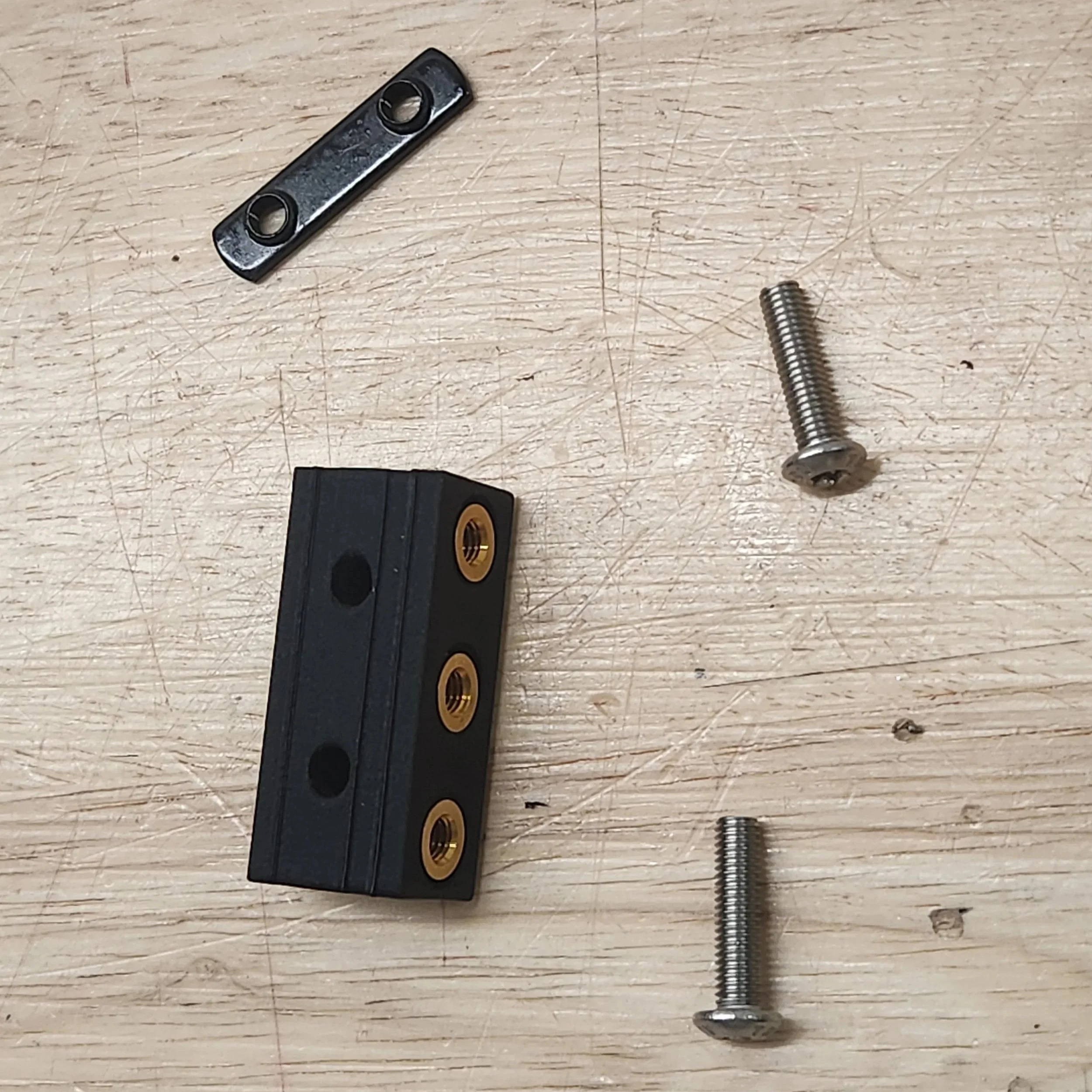
When you have all the pieces, it should look something like this:

First step is to insert the heat-set inserts into the 3D-printed rack ears. You may need to increase the hole size slightly depending on your printer settings, its a good idea to use one rack ear as a sacrificial piece to dial in your settings.
Once that’s completed, loosely insert the two screws through the perpendicular holes and loosely screw both into the double sided nut for each. Complete all 12 and set aside.
Next up, using a 1/4-20 tap, tap both ends the ends of each of the aluminum extrusion 1” deep. Be sure to use tapping oil or some kind of lubricant. Once completed, set aside.
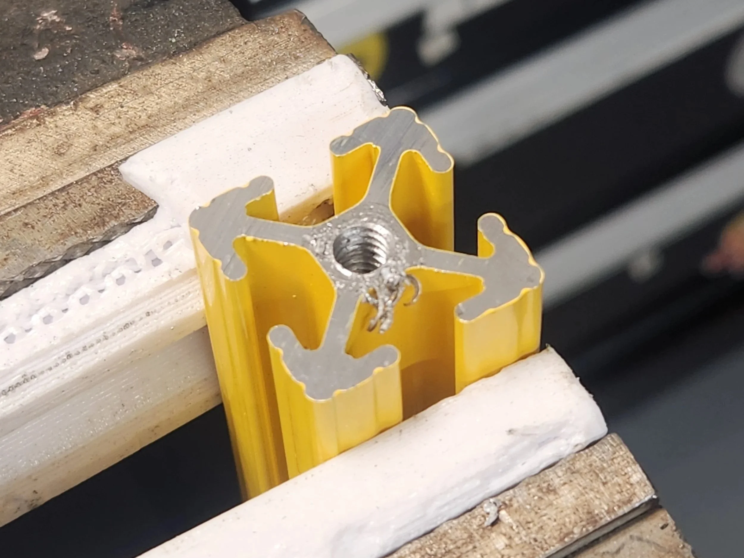
With 3D printed soft vice jaws for pzaz.
The next step is to assemble the flat plates. For both the top and bottom plates, Insert screws through the 8 holes near the 4 corners so that the head of the screw is away from the corner. Thread on the M5 T-Slot nuts so that they’re loose on the screws, they’ll be tightened later.
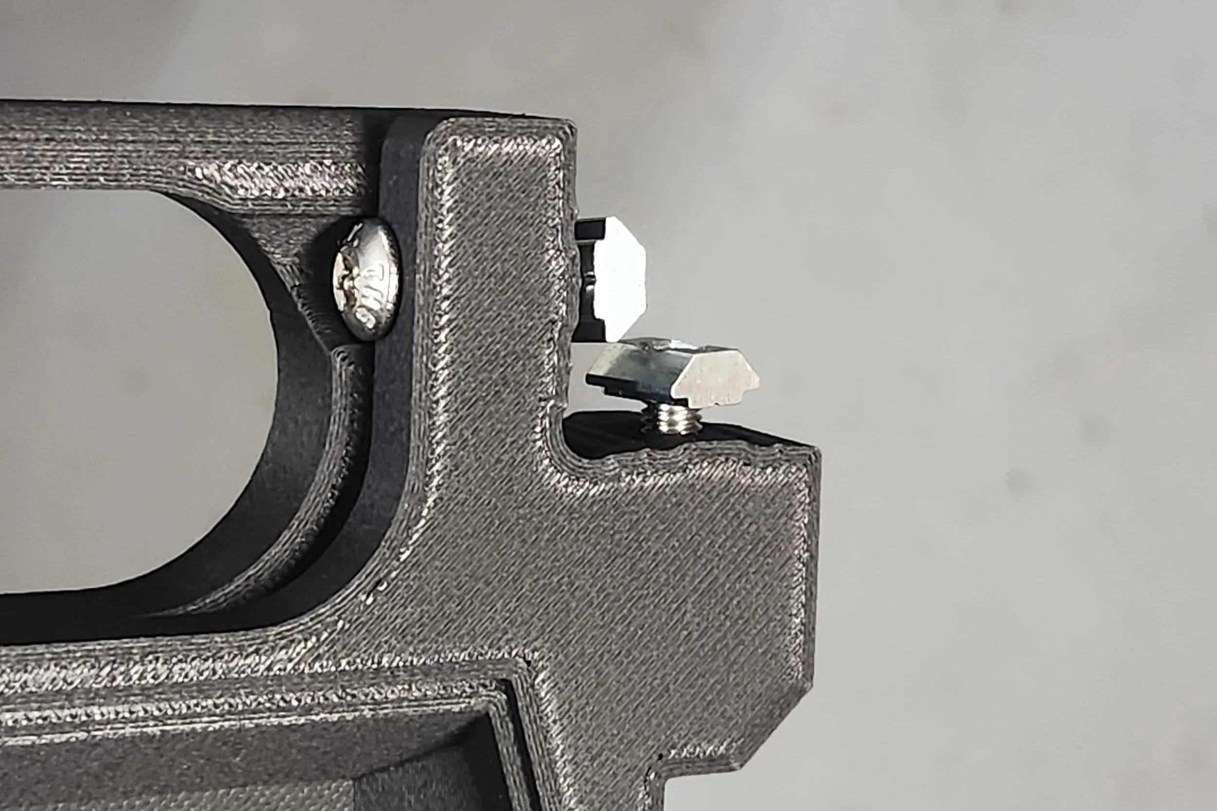
Like so.
With the bottom plate on a flat surface, with the large flat plane pointed up and the T-slot nuts aligned vertically, insert one of the aluminum T-slot extrusions into the corner so that it two of the perpendicular nuts on the corners go into the extrusion. Use a long screwdriver to tighten the nuts, making sure the raised area tightens into the slot of the channel. Repeat for the 3 remaining channels, until all 4 posts are attached to the bottom plate.


Once completed, carefully flip over the assembly so that it appears as if the plate is standing on 4 legs. Place the bottom retainer 3D-prints along the short sides of the top of the plate (the side facing up when it’s inverted) so that it covers the edge and the bottoms of the T-slot extrusion. Using 1/4-20 bolts or the rubber feet with studs, screw down the retainer piece, with the threads going into the tapped holes of the aluminum extrusion.
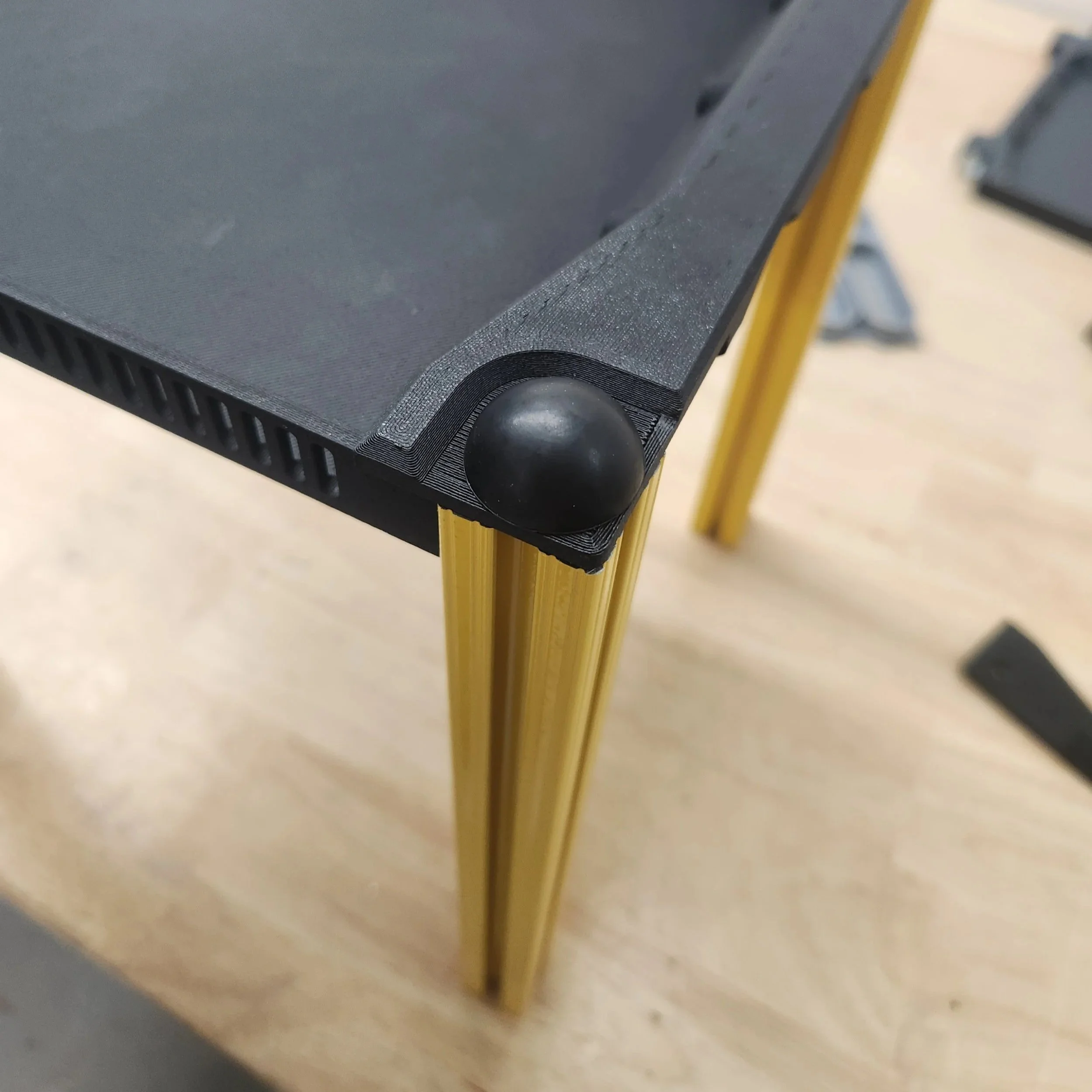
With a rubber foot installed.
With the bottom retainers installed and bolted down, flip the assembly over so that the T-Slot is pointing up. Take the rack ears assembled earlier and after identifying the front face of the rack (Which should be the face with the long edge of the bottom plate that has vent holes in it), slide the rack ear double sided nuts down the interior channel of the T-slot.

Repeat 5 times to add in the 6 rack ears for each side. Repeat that process on the flip side, and then tighten the screws down to lock the rack ears in place.

Once that’s complete, repeat the process done for the bottom plate for the top plate, facing the large flat plane towards the interior of the assembly. Screw in the handles to the top the same way as the bottom retainers, using 1/4-20 bolts and/or 1/4-20 eyelets.

And just like that, you’ve got a perfectly usable open 10” mini rack.

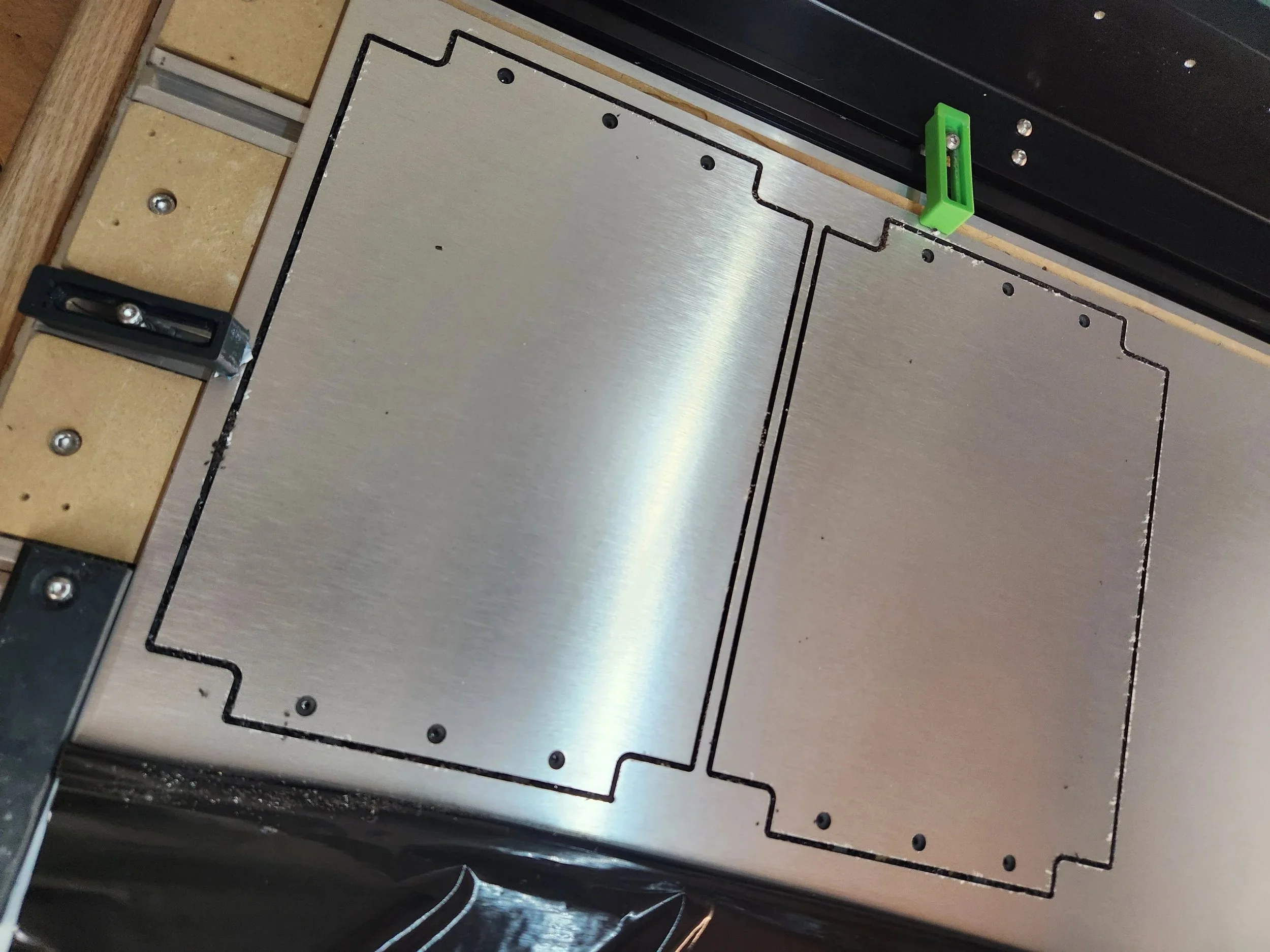
If you’d also like to make side panels, I’ve included a .dxf profile that can be used to cut them. I used ACM (Dibond) panels that I cut on the CNC. Worked like a charm.

Pictured but not completed is the door. I made a version of it, but it didn’t work as well as I wanted, so I’m going to keep tweaking it and keep working.
So without further ado, here’s the files - https://www.printables.com/model/1381613-t-slot-10-mini-rack-6u
Included are CAD files as well, if you’d like to modify / remix it.
Anyways, that’s it for now. I got use the rack this past weekend in a LAN party, and it worked perfectly. More on that later.
