
And around we go... Making We're So Over, We're So Back
I’ve always had difficulty squaring the tension in metal casting for artistic purposes. As a technique, metal casting is practiced far more by industry than by individual artists and for good reason - Its incredibly resource intensive and benefits greatly from economies of scale. And frankly, unless you have a conceptual necessity or are making sculpture for exterior installation, there are far easier ways to make objects into similar forms (see 3D printing, foam casting, etc) in place of casting metal. In industry, the function dictates material choice, and in considering the material properties of aluminum, I began to think of the various ways in which heat could activate a cast piece. Ultimately though, I didn’t have a use case for the idea, and filed it away.
That is, until I started to consider the function of the work that became We’re So Over, We’re So Back, whereby a computer would be running a program where two bots fought in an looping first person shooter match, and I started to think of how I could build the computer as an formal aspect of the presentation. My thought process went a bit like this…

‘Just as
Looping first person shooter…
Looping game…
Looping…
…
Water cooling loop!
And with that I was off to the races.
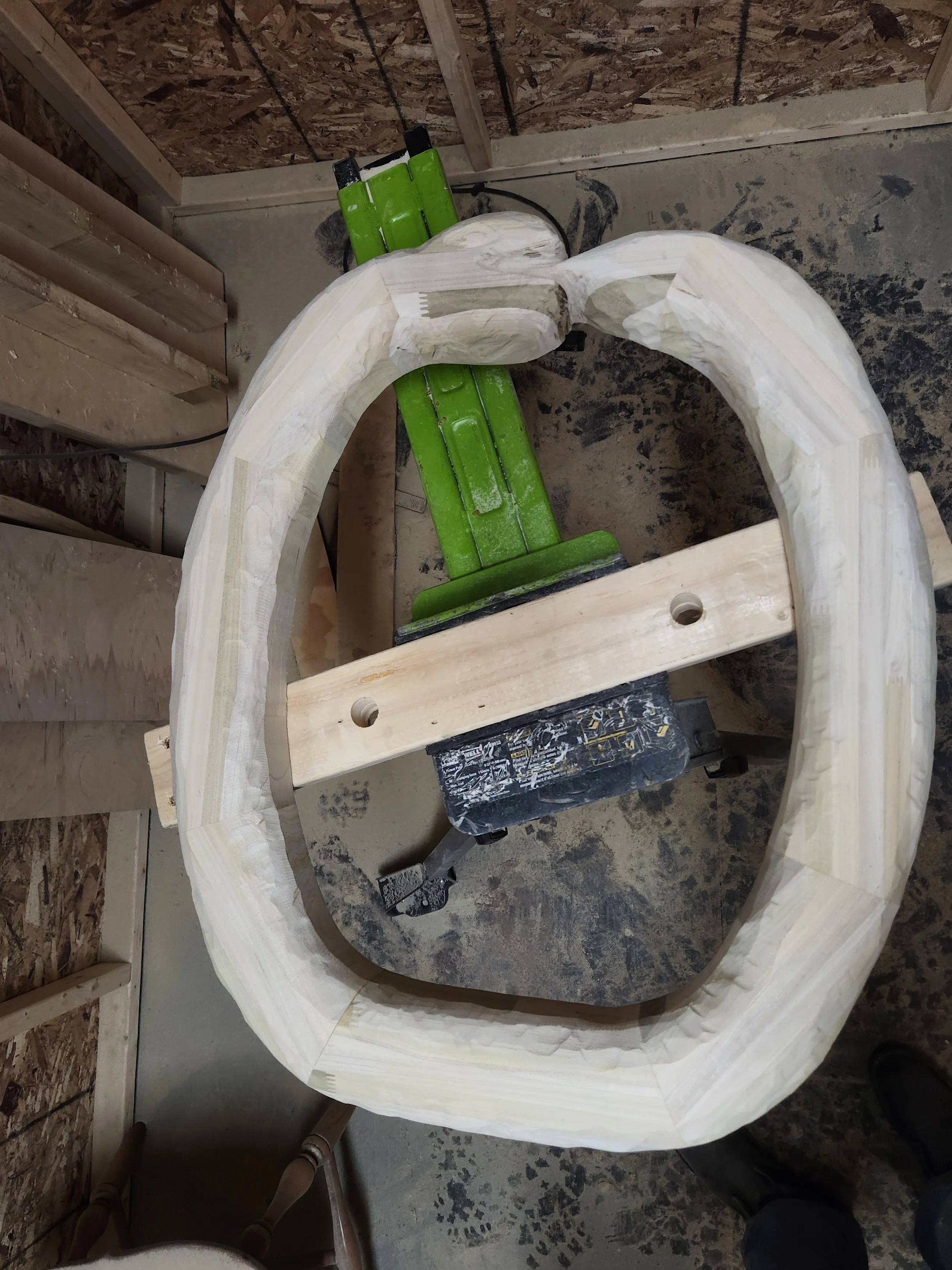
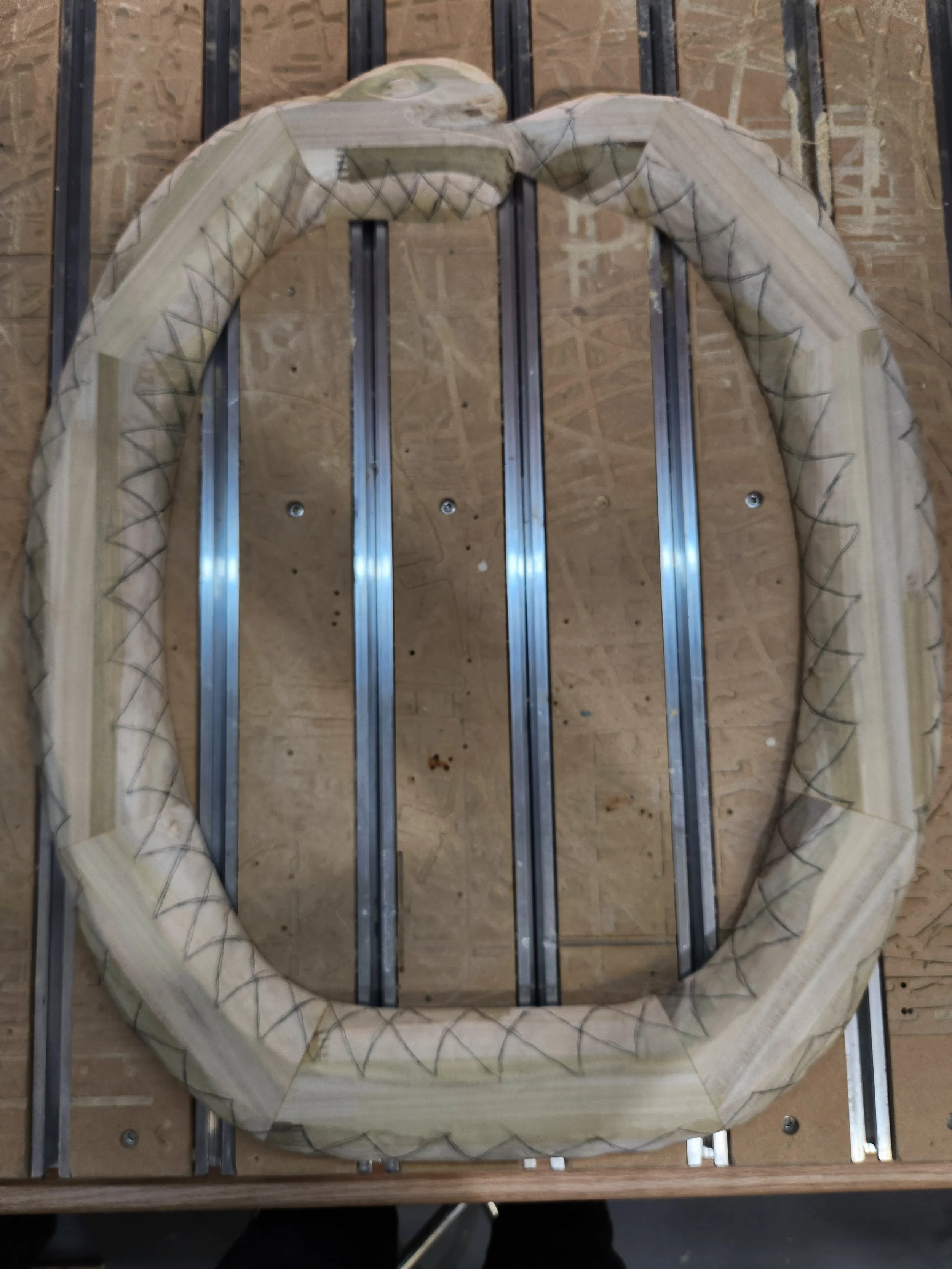
To start out with, I needed an initial design. Drawing from the concept of endless birth/death/rebirth I settled on the motif of the ouroboros, and started figuring out how to make the positive. I knew I was going to be sand casting, and with that in mind I settled on a wooden pattern. After doing a few initial layout mockups using cardboard PC component profiles, I determined I needed a loop about 30” tall by 24” wide, and got to work.
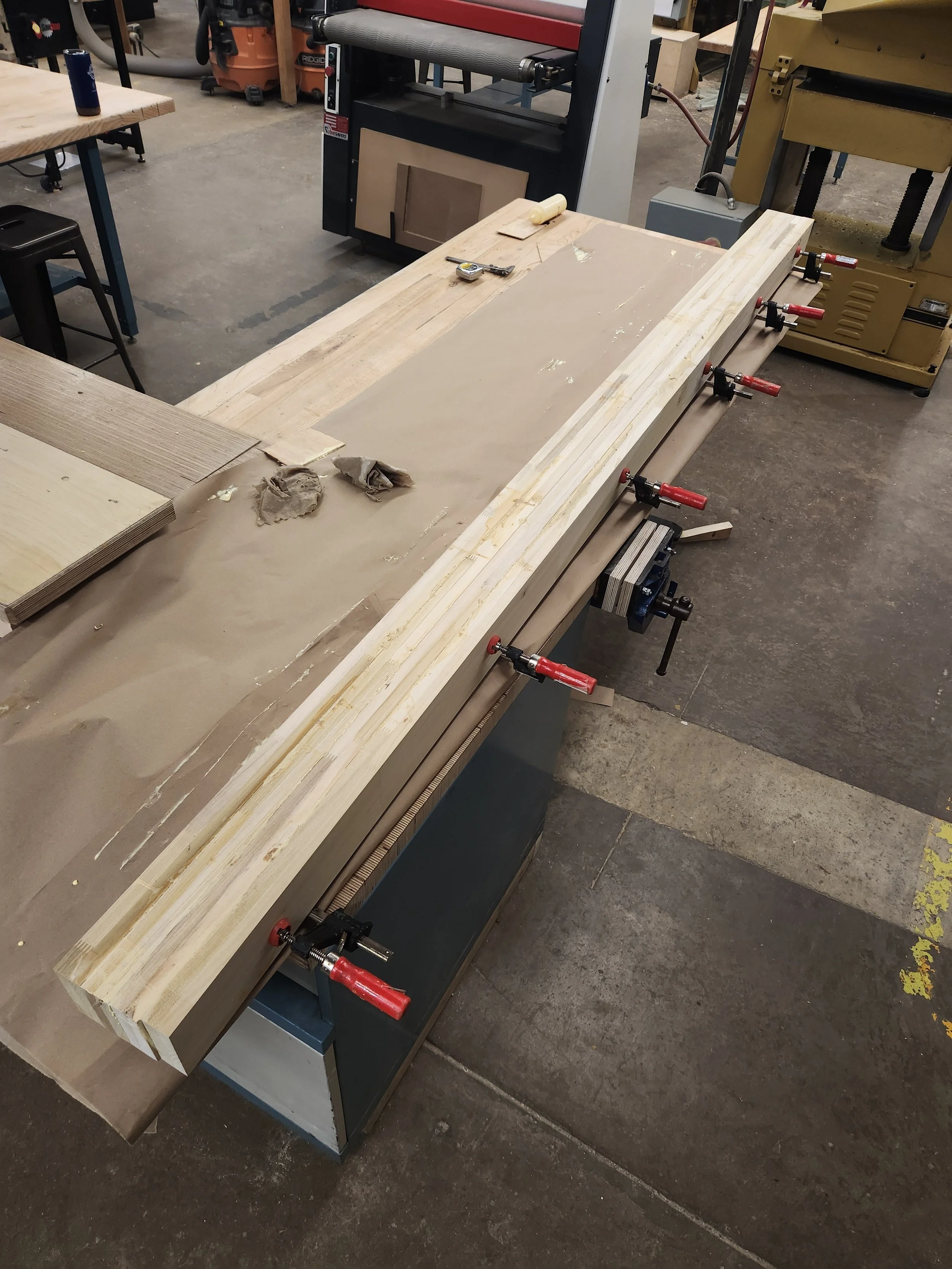
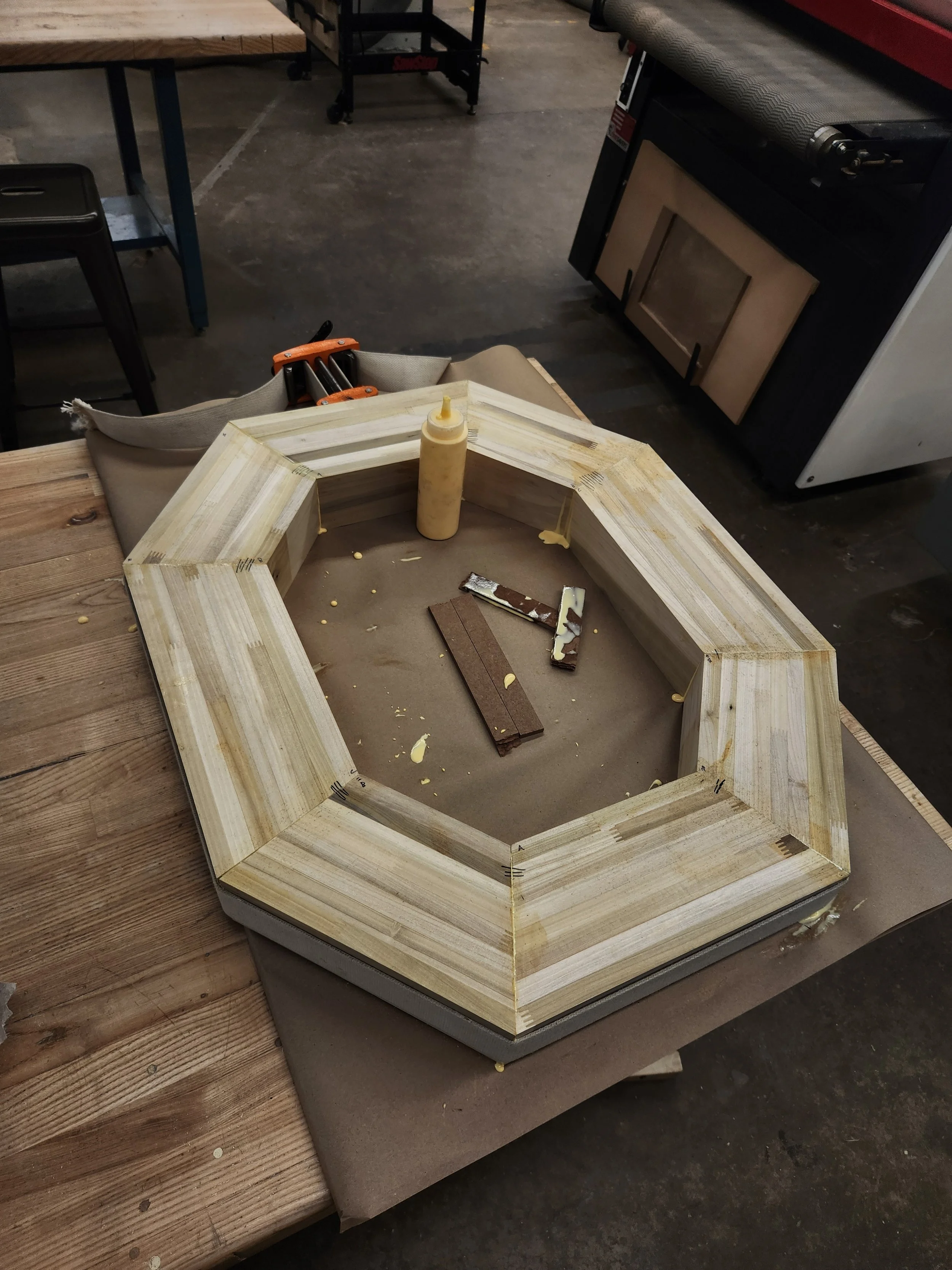
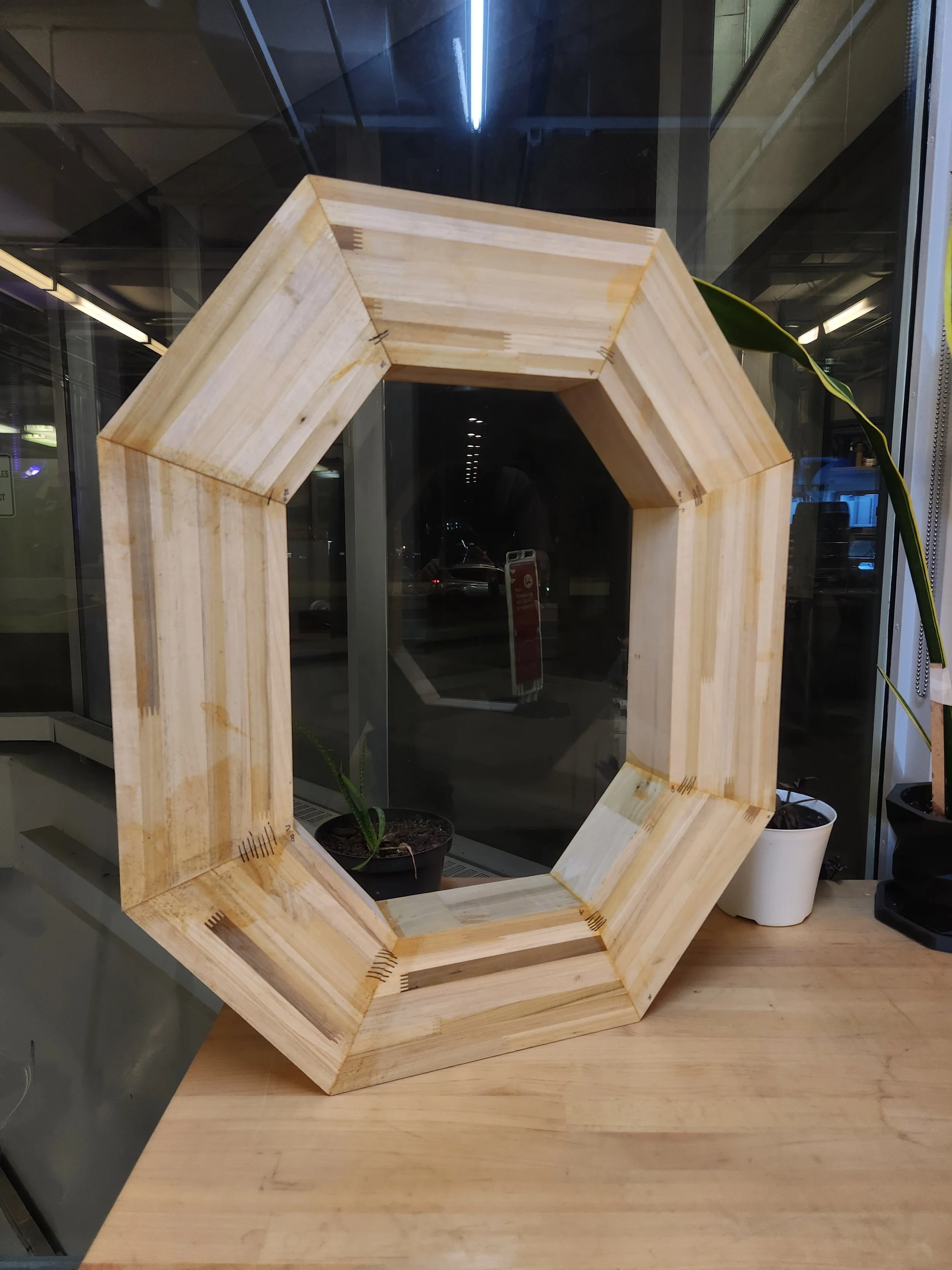

With the stock ready, I tried my hand at a bit of power carving…


And with the pattern complete, I was able to move on to the casting. I’m lucky to be well integrated into the local scene here in Chicago, and was able to coordinate an aluminum pour in coordination with a few friends. After buying most of a ton of silica sand and a two-part resin binder, we were ready to mold…
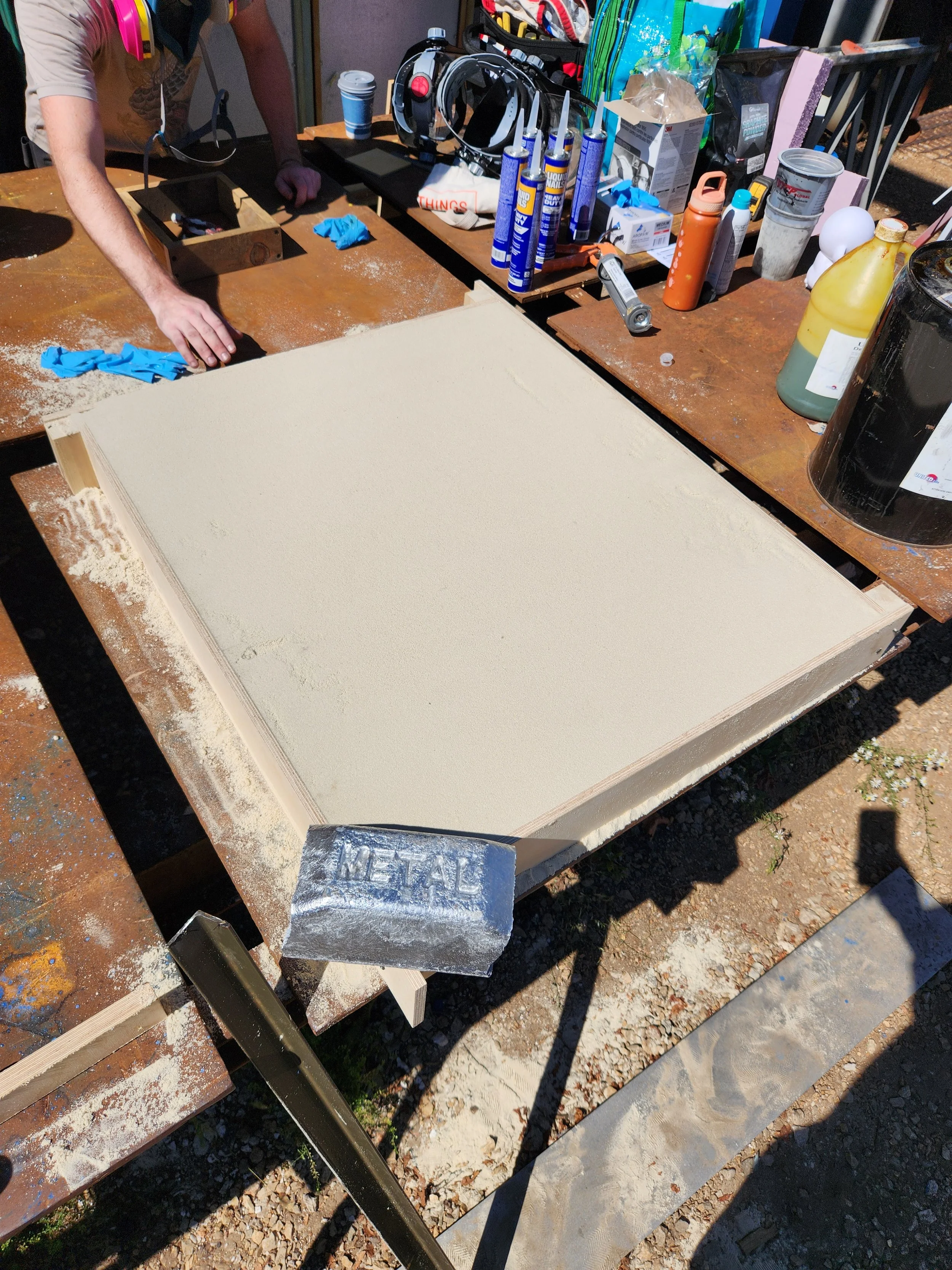


Thankfully, for aluminum, it’s a pretty low temperature (we melted at ~1400f) so a propane furnace was more than sufficient. This mold took most of a #50 crucible (50 lbs), but filled up well with some minimal* porosity at the intersection of the pour spout and the model.


And with a bit of cleanup and removing the gating & venting, I had a very usable casting that came in at just over 30lbs.
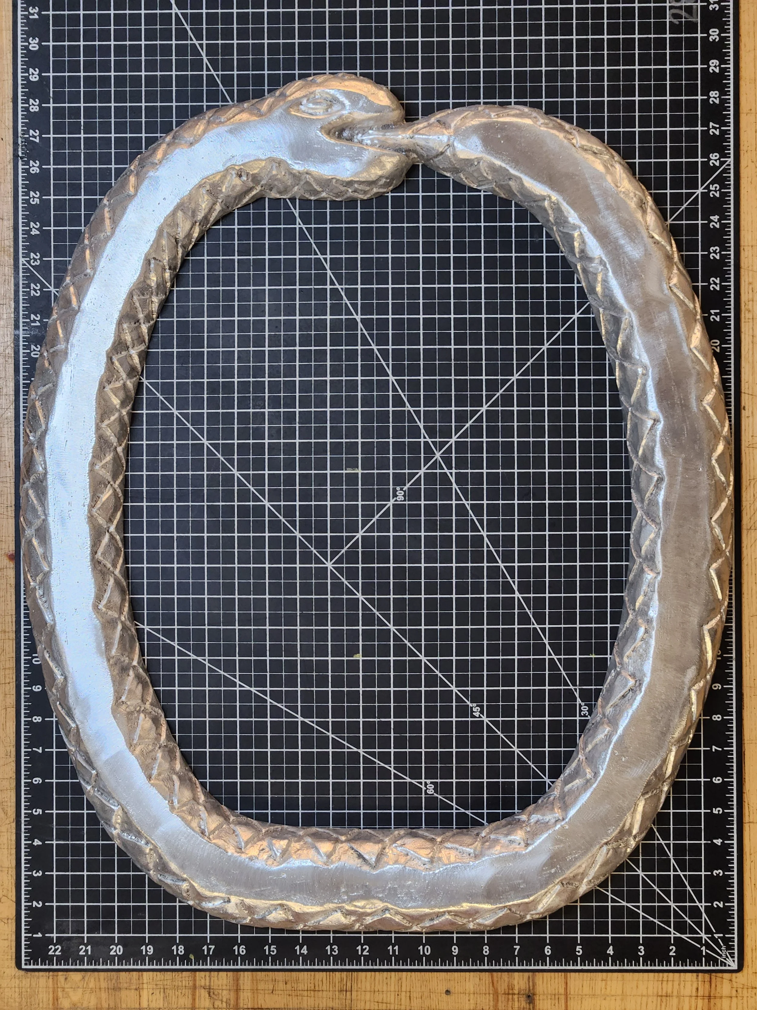
Nice
Now came the fun part - tests, tests, and more tests.
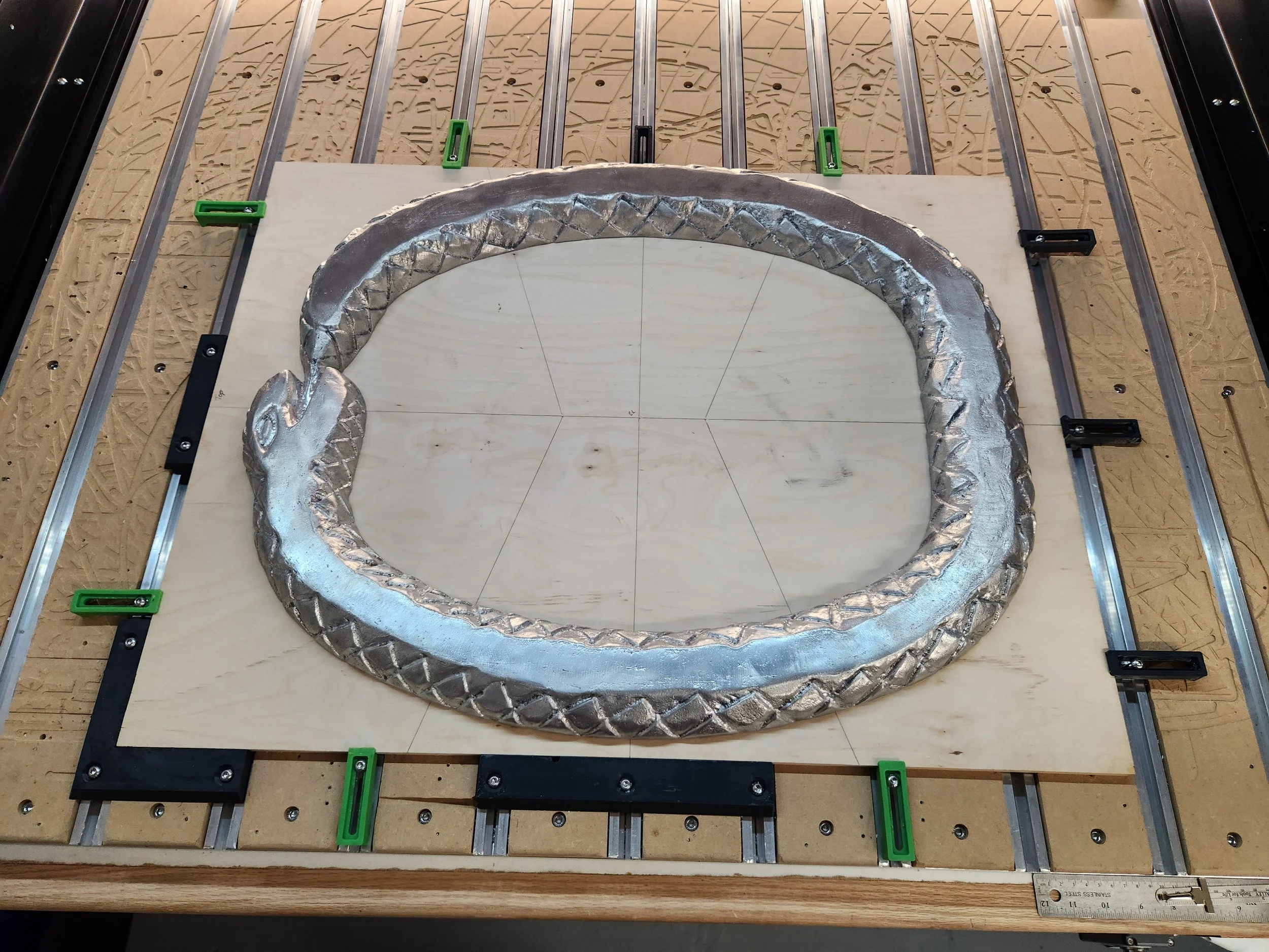
With only one casting to my name and a million different ways to render it unusable I started the process of figuring out how I was going to incorporate in a sealed channel for the liquid that be running through the water cooling loop. I knew these would need to be precise, so I settled on using my CNC router to do the machining. Up until this point I’d only cut non-metallics on the router, so my first order of business was to dial in the settings for aluminum. Thankfully the alloy we cast was amenable to machining (319 AL), and after running a few cut tests on ingots, I was ready to clean up the front face the casting.


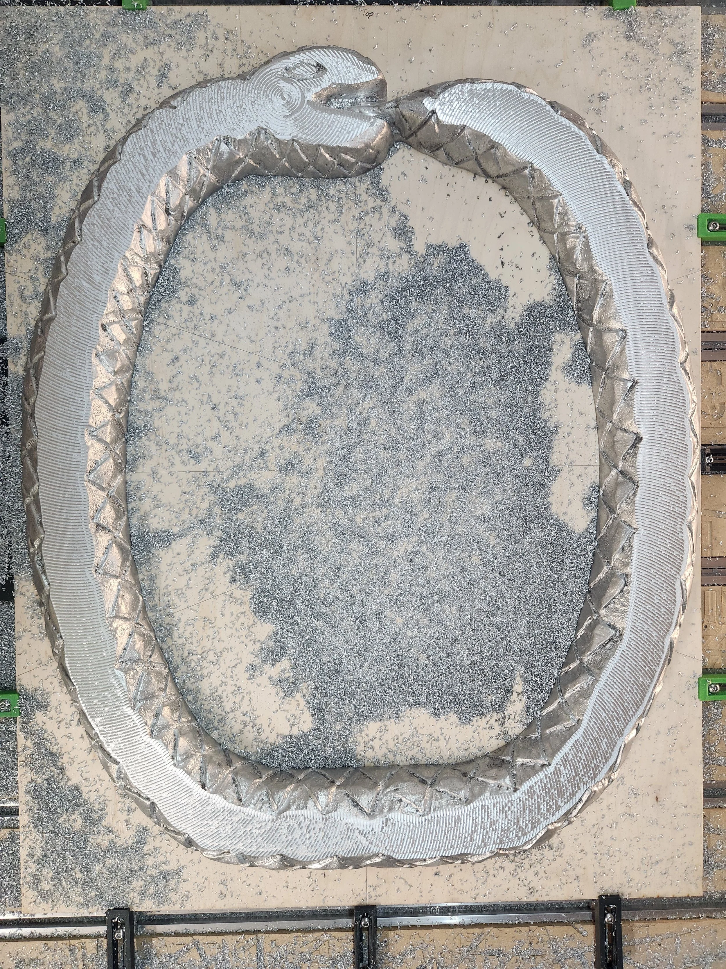
The surface finish was passable for my purposes, but not great. I ended up revisiting that.
And with that complete I was able to digitize the top profile of the casting and bring it into CAD. to get an accurate profile from this very organic shape, I laid blue tape across the entire top surface of the casting and cut it so it would be a 1:1 of the top face of the casting. I then printed off a 24” wide 1” grid on a plotter and carefully transferred the blue tape onto the grid, making sure to not crease it or stretch it. After that was done, I hung the paper on the wall and used a telephoto lens to photograph the paper+blue tape.


To correct for distortion, I brought the photo into lightroom and corrected for lens distortion using the alignment tools. From there the photo was adjusted for contrast in photoshop and minor cleanup, and then brought into illustrator for final sizing and path tracing to give a vectorized version of the tape profile. Because of the printed grid on paper, it was a snap to adjust the sizing to the correct dimensions and the grid was a known spacing.

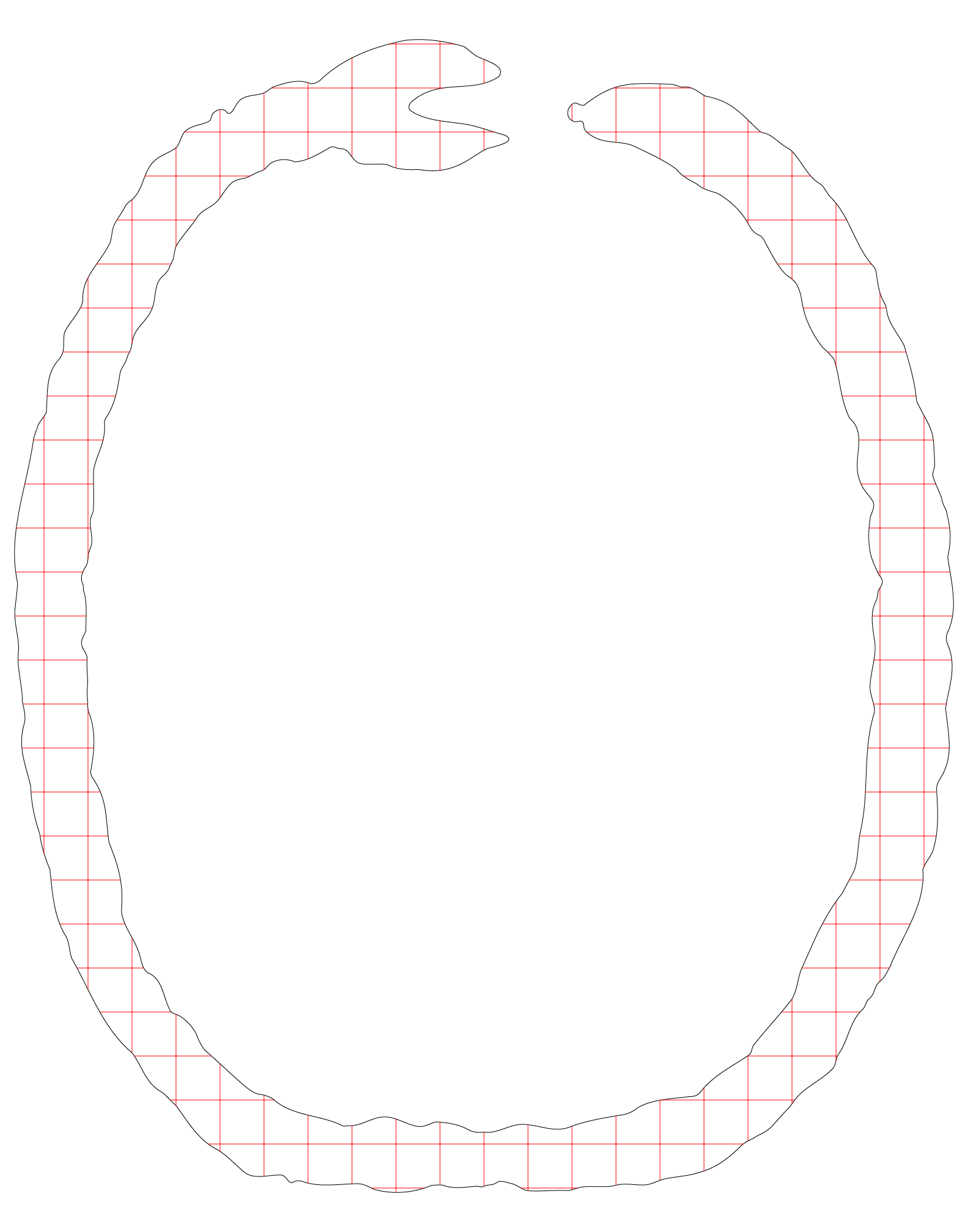
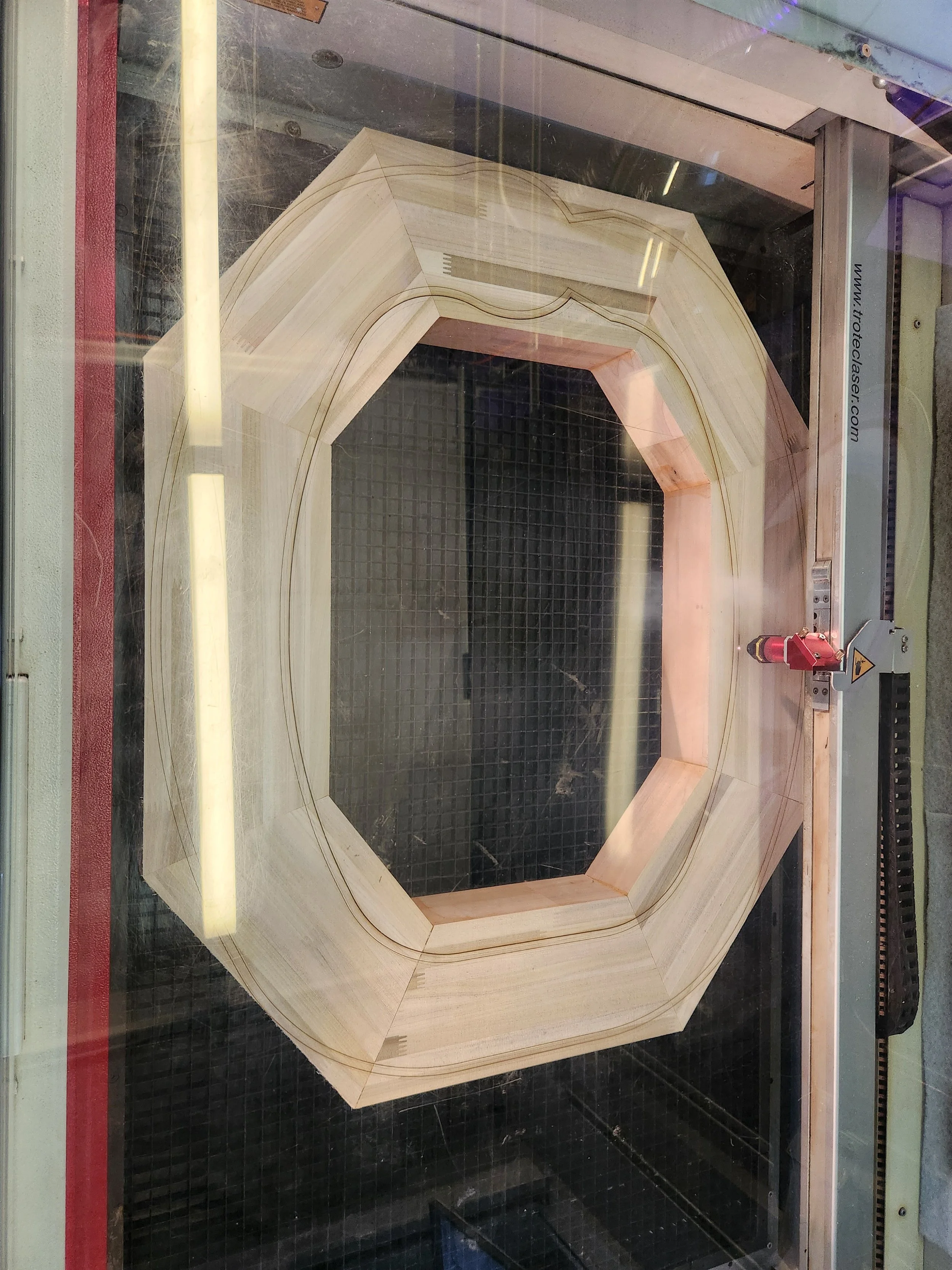
Once that was complete, I laser cut out a template of the digital file to check for accuracy. After a few revisions, I was happy with the profile and brought it into CAD.

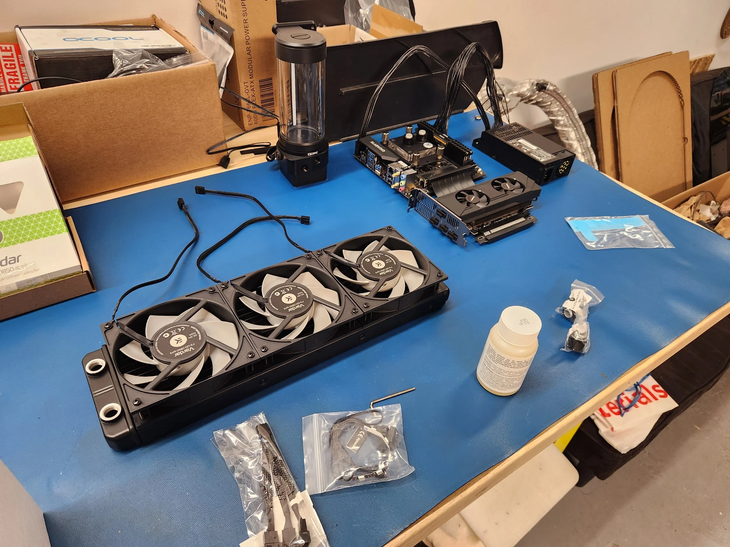
Concurrent to all of this finishing work on the casting, I also worked on figuring out a few more specifics of the water cooling loop. I’ll fully admit to this project being wish fulfillment in addition to a project, as this would be my first time ever making a water cooled PC, despite having admired them since my teenage years. With that in mind, I dove into the process of how to make a functioning loop… Which is when I quickly discovered that in my haste to make the casting, I’d made a decision that was going to dramatically complicate the rest of the water cooling loop.
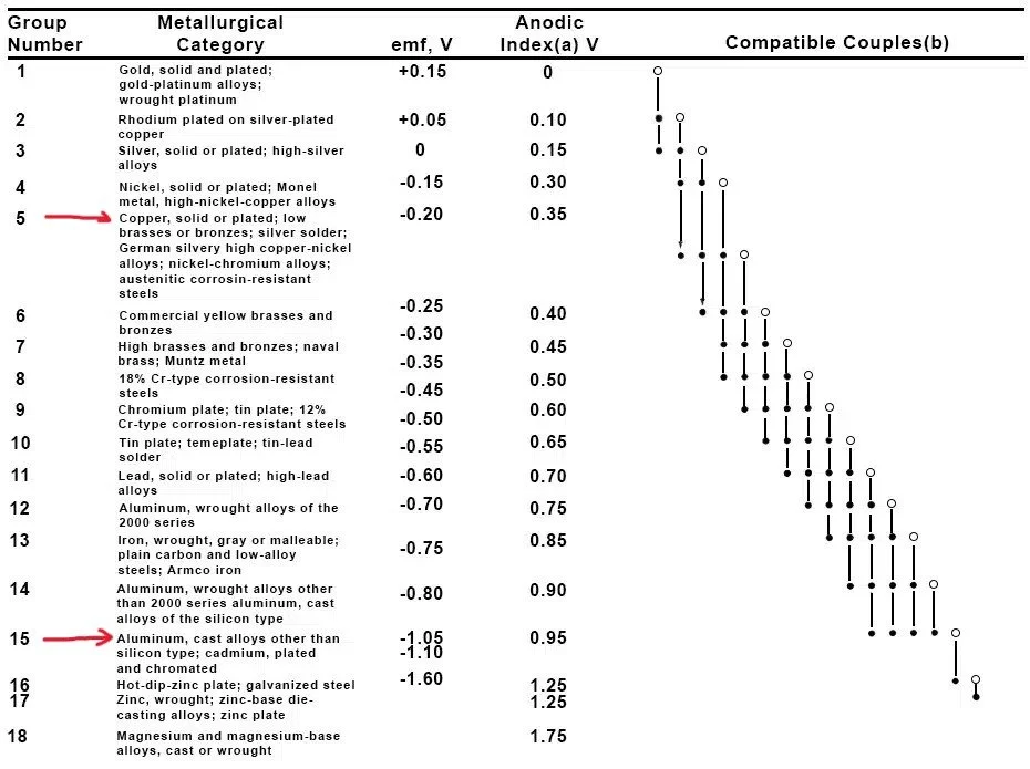
Fig. 1 - Galvanic corrosion series.
See, when dissimilar metals come into contact with liquids, especially water, a funny thing called galvanic corrosion happens. Basically, metals have an innate charge to them, and if the difference in charge between metals is substantial and an electrolytic carrier (water + dissolved ions) + a charge is present, then metals will with a higher charge will migrate from the liquid contact surface to the metal with less of a charge, usually taking the form of a dark gunk that clogs the fine features of the fins in a heat-transfer block in a water cooling loop. (If you’re interested in learning more about this, Practical Engineering on Youtube)
Nowadays this isn’t really an issue for those building water cooling loops, as the suppliers for PC cooling components have settled on components almost entirely made around copper, selected for its high thermal conductivity. However, I’d just made an integral part of this piece out of aluminum, which if you’ll consult the chart (Figure 1) , are incompatible with anything copper. Which, had I been building this PC 10 years ago, probably wouldn’t have been a problem. However, the industry actively dissuades using aluminum components now, so I was in for bit of a hunt.
There are 4 main components types in a water cooling loop (beyond pipes/tubing) that use metals:
The blocks - the components that come into contact with the heat generating components such as the CPU / GPU, and transfer that heat into the liquid.
The radiator - the component that received the hot liquid and disperses it into the environment through forced air or IR radiation.
The fittings - the pieces that connect the tubing to the various components of the loop, which can include angle adapters and compression or barb fittings for the tubing.
The pump - used to circulate the liquid through the loop, sometimes there are screws or a baseplate made out of metal make contact with liquids.
Of which I already had an aluminum radiator, so I’d need to find AL compatible blocks, a pump, and fittings.
After a few weeks of searching, I was able to find the answer. Around 2017, the company EKWB put out a line of budget water-cooling kits called their Liquid Gaming line. One of the cost saving measures of these pieces were the use of all aluminum compatible hardware, fittings and all! The one downside - they’d discontinued line in the late teens, so I was going to need to do some searching. Thankfully, a few Newegg vendors had backstock of soft-tube Liquid Gaming angle fittings and barb adapters, and eBay was able to provide a single listing in Canada for an unopened liquid gaming kit, complete with aluminum CPU block.
That said, I’m not sure I’d be able to remake this piece today if I wanted to. The aluminum CPU block was difficult to find, and I’ve not seen another liquid gaming kit come up on eBay.
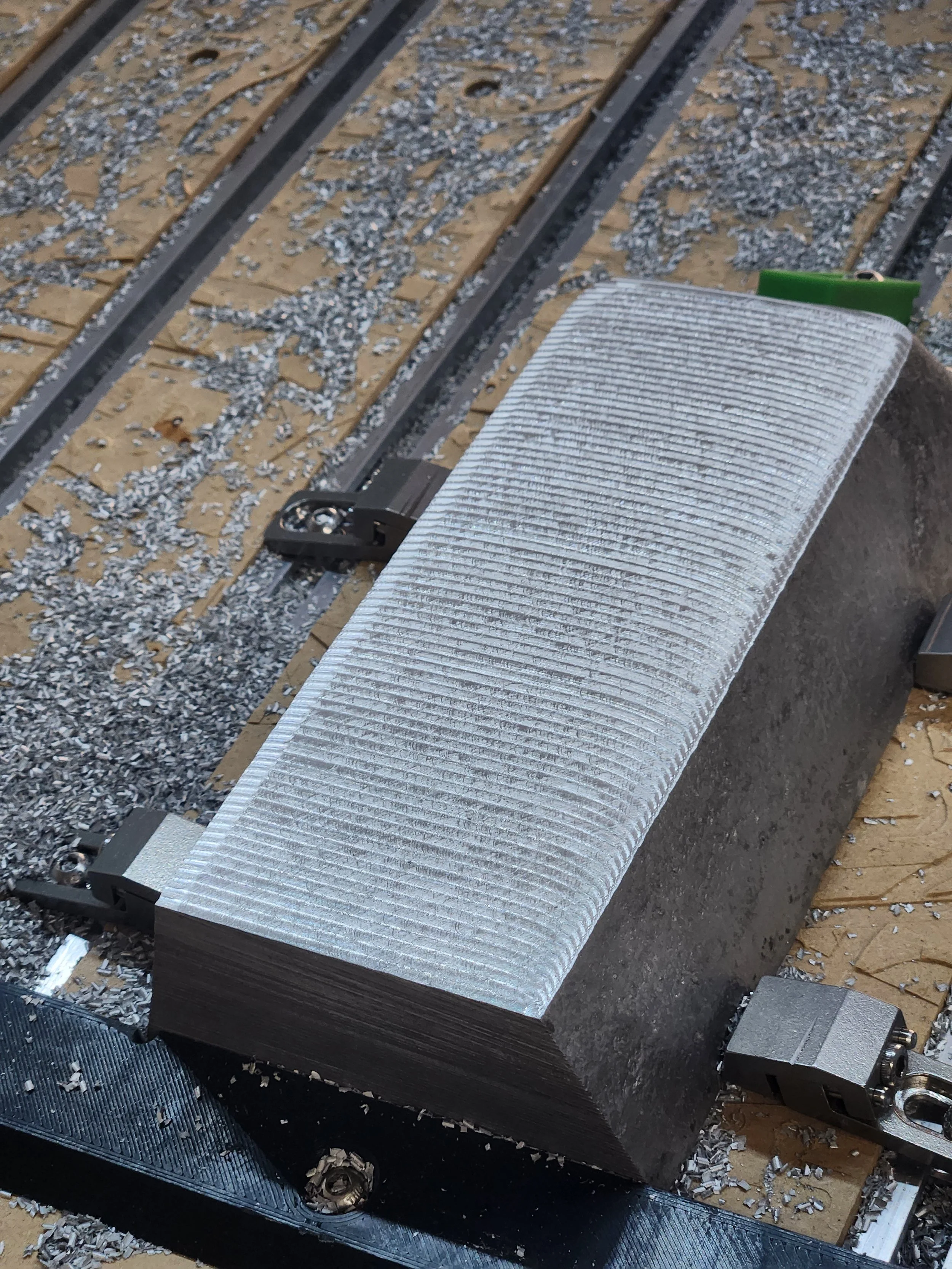
With that complete, I was able to work on a proof-of-concept prototype. I needed to dial in the settings for the liquid channel, gasketing, and screw holes, so with a spare aluminum ingot, I got to work. The first step was to resolve the surface finish of the parts, so I started by tramming in my spindle and purchasing a 14mm surfacing tool.


Much better surface finish. I put together a quick liquid channel pattern and after more than a few 1/16” endmills breaking, I dialed in the feeds & speeds and finished the test cuts


From there, I added in a few 2.5mm holes to tap for M3, added a gasket channel, and cut out a polycarbonate cover to cap the channel.


And with that, I was ready to test. I set up the block on a few paper towels with a bright green liquid coolant and let the pump circulate the liquid for a few days.


The sharp eyed amongst you may have spotted an issue within the center photo of the testing - There’s micro-fractures around a few of the flush mount screws…. This became a bit of a problem.
For the initial clear caps, I’d selected extruded polycarbonate for its ease of machining and its impact resistance. It cut beautifully, and was very easy to countersink, but after hand tightening the screws and letting the AL block heat up with the pump, the areas around the screw holes started to fracture. I didn’t think it was a big problem at the time*.
In addition, after my first test I noticed that the paper towels had evidence of green fluid on them. After narrowing it down (and 4 gasket types later), I determined that I wasn’t using the correct type of gasket material in the channel, and that I’d slightly oversized the cut channel in the aluminum. After bumping up from a 3mm gasket to a 3.5mm gasket and changing from a 70A shore hardness to a 50A shore hardness, the leaking from the gasket stopped completely.
And with that, I moved onto milling in the channel + tapping the final piece.


140+ 10mm deep M3 tapped holes, and not a single broken tap. Finally I cut + tapped the polycarbonate face.


And with that I was ready to test. To do so, I set up a pump and let it run for a few days. Almost immediately there were issues.


Once I’d tightened down the flat head screws to the appropriate torque to hold the liquid in with the gasketing, it caused the polycarbonate to deform and eventually crack, leading to large leaks from the casting. I’m pretty sure this was because of the stresses imparted on extruded sheet + micro fractures from the CNC cutting. In addition, I also discovered that porosity in the casing at the bottom of the loop (directly underneath where the casting pour cup was located) was leaking fluid out of the back of the casting.
So after multiple trials runs and tests, I settled on using laser cut cast 1/4” acrylic, cap screws installed with a calibrated torque wrench, and sealing any areas of porosity by applying a 2 part sealing epoxy. After 8 successive disassembly / reassembly loops (including unscrewing and re-screwing all 140+ screws), It finally held water without leaking.

Up until this point, I’d been proceeding with the hope that this casting would actually function as a radiator. With the loop watertight, I could put that assumption to the test.
For those curious, the PC components I selected were:
CPU: AMD Ryzen 5 5600
MOBO: Gigabyte A520I
RAM: Corsair Vengeance LPX 32GB (2 x 16GB) DDR4-3200
GPU: Gigabyte RTX 3050 6g OC
SSD: Crucial P3 Plus 500GB
PSU: Enhance ENP-7660L-OVT - 600W
CPU Block: EK Supremacy AX
Pump+Reservoir: XSPC QX5 Photon 170
Liquid: EK-CryoFuel Solid Scarlet Red
Radiator: custom :>
A 12 core modern CPU was definitely overkill for my use case, but I figured having a CPU that would run with a lot of headroom would help cut down on thermals. Plus, Microcenter had a pretty screaming Black-Friday sale.
Once the components were all assembled, I looped them into the 360mm radiator that came with the Liquid Gaming kit to get a baseline heat reading. After installing a lightweight Linux distro (EndeavourOS) and installing a CPU stress tester (stress-ng), I ran a few tests and recorded CPU and liquid temps (measured with a thermocouple in the reservoir) .


The temps with the 360mm radiator were: max 28°C CPU/ 26°C liquid idling and max 35°C CPU / 32°C liquid with a single core 100% load for 6 hrs. Pretty good!
Next I plumbed in the ouroboros and gave that a few tests.

The temps with the cast ouroboros were: max 37°C CPU/ 35°C liquid idling and max 51°C CPU / 40°C liquid with a single core 100% load for 6 hrs. Not nearly as good as the purpose built radiator, but very much good enough for my purposes.
One last order of business was to install a few drain plugs into the casting. After multiple fill and drain cycles, I realized just how convenient a few well placed plugs would be. To do this, I used the CNC to cut in a flat and a through hole on to intersect with the liquid channel through the back of the casting, and then tapped it for a BSPP G1/4-19 plug.


You can see in the first image the extent of the porosity of the casting. Thankfully a thick coat of surface sealer filled in all of those holes.
With that complete, I moved over into CAD for a while and modeled all of the components going within the ring. I needed hole locations for the backer board as well as the dimensions of all the computer components so that I could design some of the brackets and cover pieces around them.
This took a long while, as I ended up needing to reverse engineer quite a few of the components so that they’d be accurate in CAD. For this project alone, my design time alone came out to 68 hours. For those objects I was able to find meshes for, I was able to build them out as components with construction pieces (such as points and sketches) that were scale accurate that I could reference dimensions off of, which worked well. I also was able to make a rough 3-D scan of the ouroboros as cast and bring it into fusion.


Thankfully, one of the benefits of working digitally was the ability to cut a test piece quitckly using a laser cutter to double-check dimensions. One of the main pieces I needed to make was a backer board to mount everything on, and prior to the final piece, I cut a few out of cardboard to check hole location. The final version was made out of a 6mm ACM panel, which cut beautifully on the CNC and was quite a bit lighter (and cheaper) than a similarly sized aluminum sheet. Plus, it tapped well and was very rigid.


From there I also ordered in a few laser cut 1/8” aluminum brackets to attach the mounting cleats to. Ordering from SendCutSend was a breeze, and to save time I ordered them without tapping, as by this point I was getting down to the wire.


And from there it was a whole lot of 3D printing. The power button mount, the HDMI outlet, the IEC power inlet, and all of the component covers were printed and some attach with a heat set insert through though the back.


The component covers are a little tricky, as to get the mesh pattern I ended up using modifier meshes in Prusa Slicer, and setting any areas that contained an intersection of the main model body and the modifier to print without top & bottom layers. That left only the infill remaining, a 30% honeycomb pattern. For instance, the below cover I exported as 5 separate bodies in a single .3MF file. The main body - grey, the “mesh” modifier - green, and a few support enforcers - red.


All told, the 3D prints took around 56 hours of print time, with a few pieces going through up to 5 revisions to get all the dimensions correct.
The last piece of custom work was the wiring. While I planned in a few spots for PSU cabled to be routed, I hadn’t planned on needing to modify cables to get them to reach. Thankfully the PSU I’d ordered was supplied with two sets of each cable type, so I snipped one end off each and mated the long ends together to extend each cable. This was nerve wracking, as the pinouts of the supplied cables were non-standard and if I miswired the ATX PSU cable, there was a good chance I could short out everything connected to the motherboard. So I took my time with a multimeter testing for continuity and labeling every wire prior to cutting. I also took the chance to wrap the cables in sheathing.


And with that, it was onto assembly and a first power on. After attaching all of the PC components to the backer board, wiring them in, and plumbing in the water loop connections. And once I attached the cover pieces, it was finally able to do a full test of the system.


It powered on first try, no rewiring needed. And no leaks to boot!
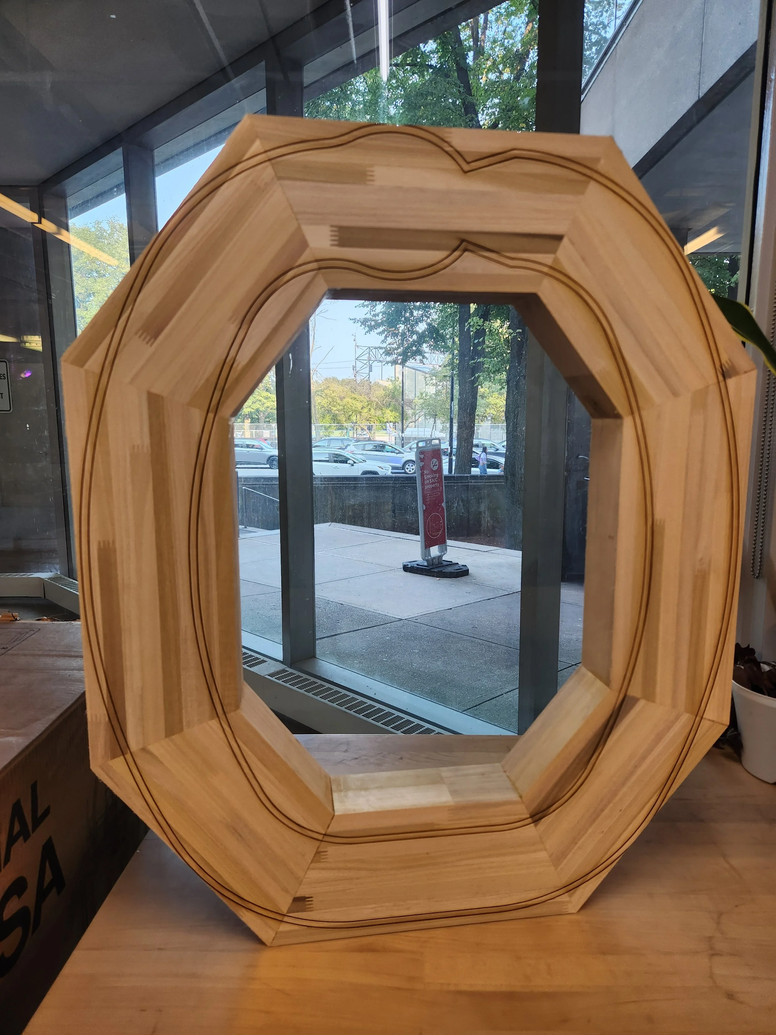
And with that, the physical aspects of the piece were complete.
I’ll be covering the software in another blog post, so that’s all for now. Very happy this piece is up and running, and in the world.
At the time of writing (mid July 2025) this piece is installed at Bert Green Fine Art as part of my solo show DEATHMATCH, presenting a body of work all about virtualized violence and simulations of war. If you can make it, it’d be great to see you there. :)
That’s all for now, Cheers!
- Mac P.
